1. Kinetic Sculpture
Throughout the second and third week, we were taught a range of essential skills and techniques with the equipment within the lab. For instance, we learned to use hand saws, and other tools such as vernier calipers, hand files and the bench grinder. In addition, we were also familiarized with using the hand drills and drill presses. With this given knowledge, we were tasked to create a kinetic sculpture.
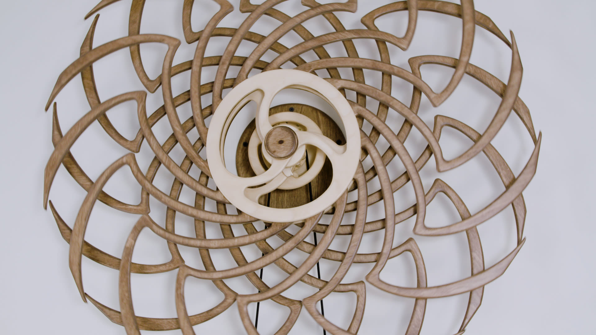
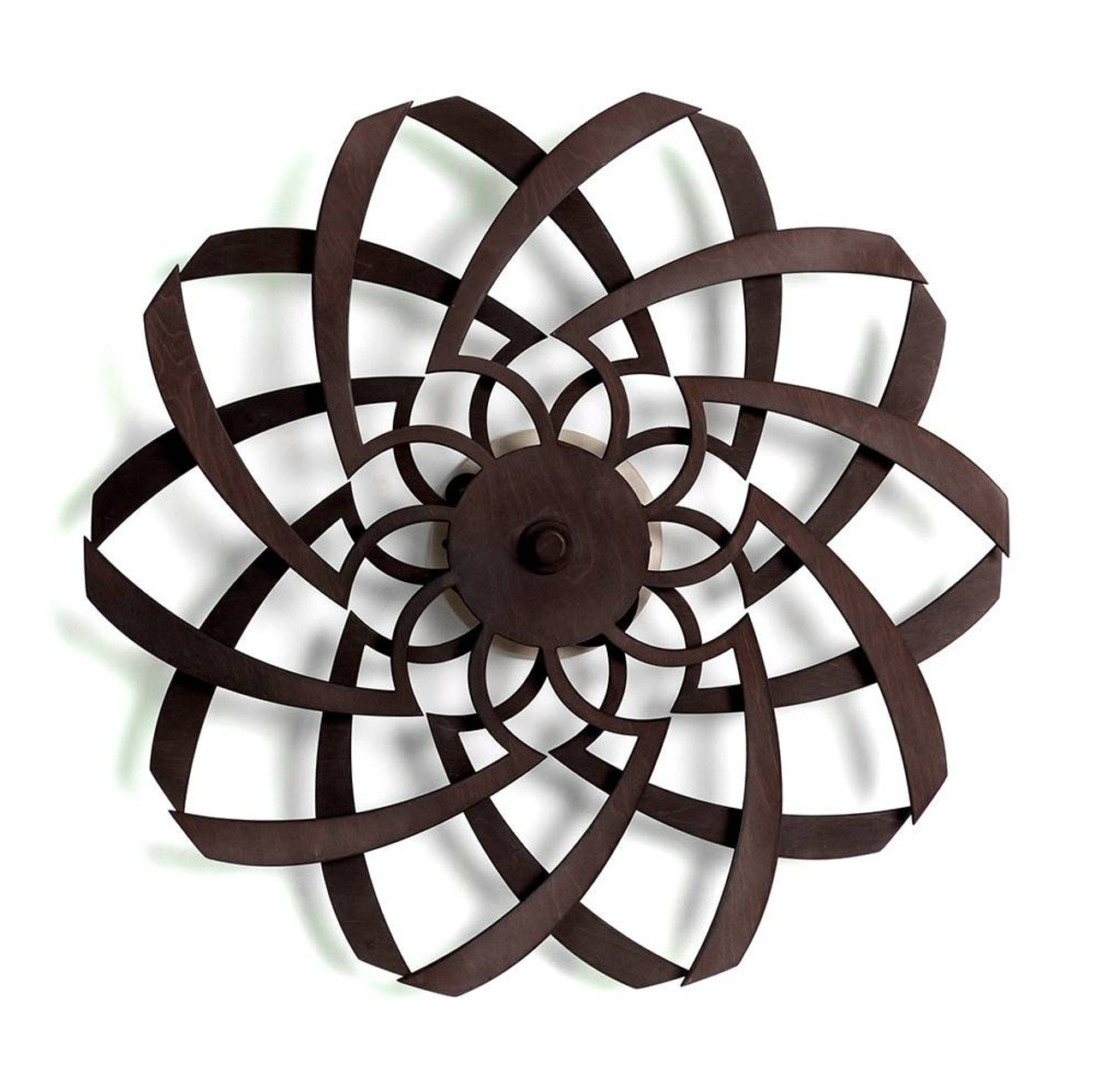
The two photos below served as inspiration for my kinetic sculpture, as I attempted to create a rotating device that would move an interesting shape to create an optical illusion.
Design Phase (Fusion360):
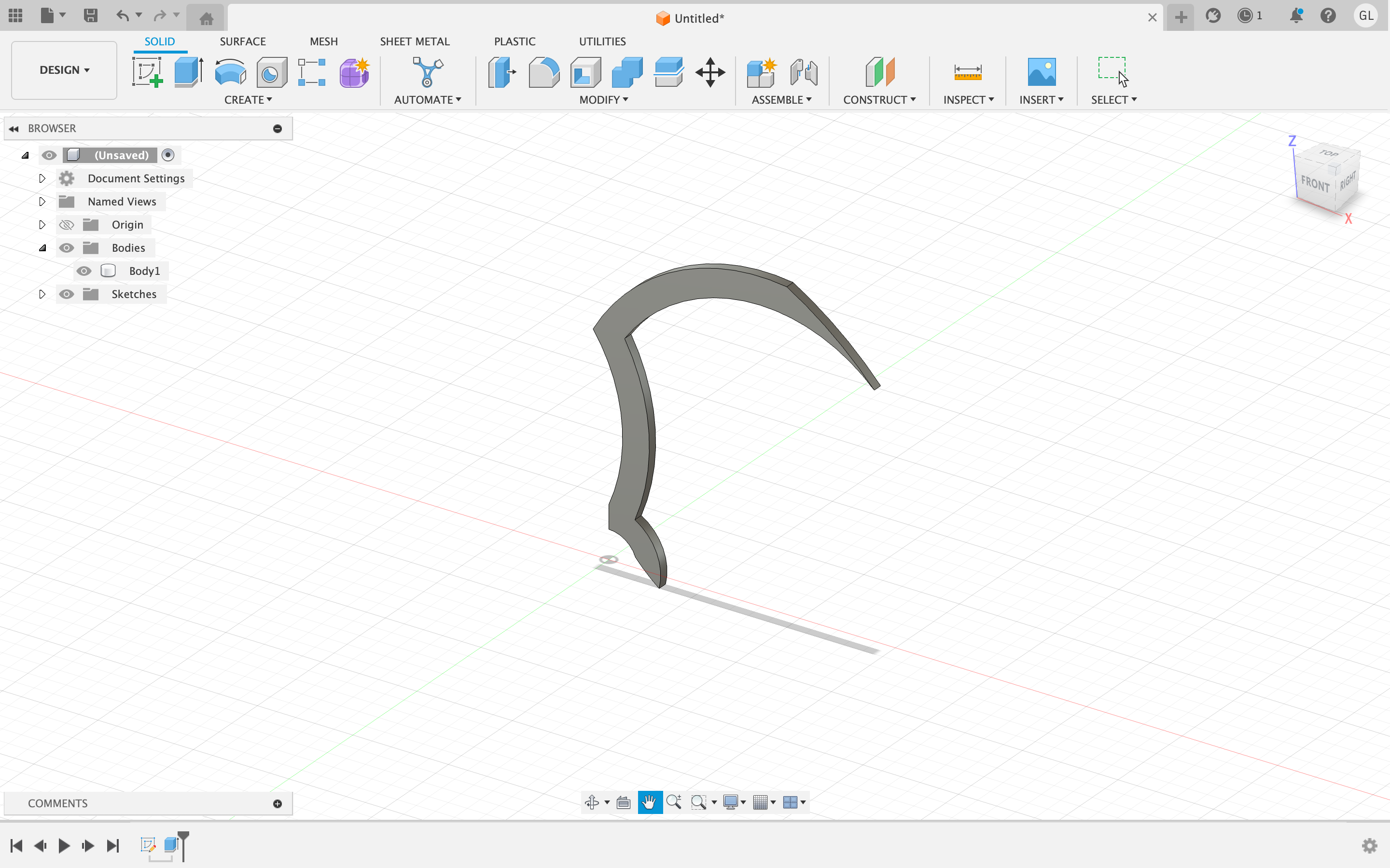
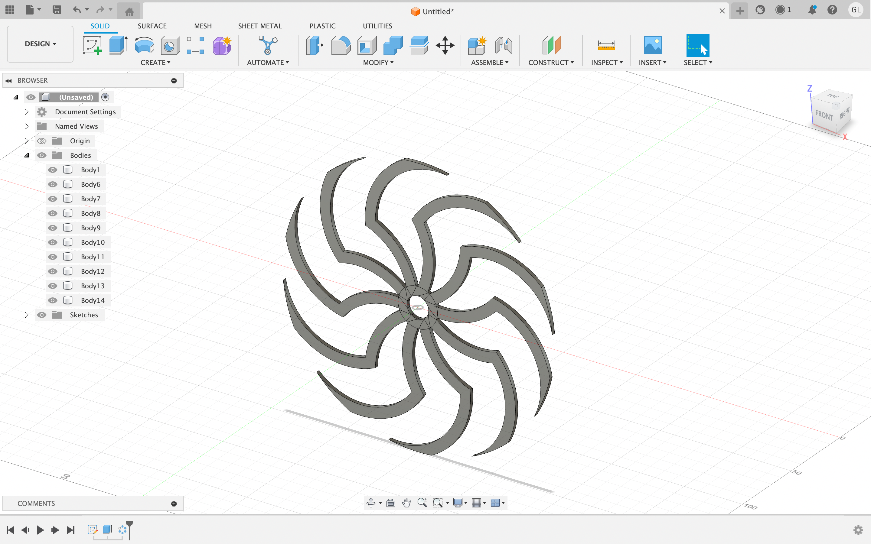
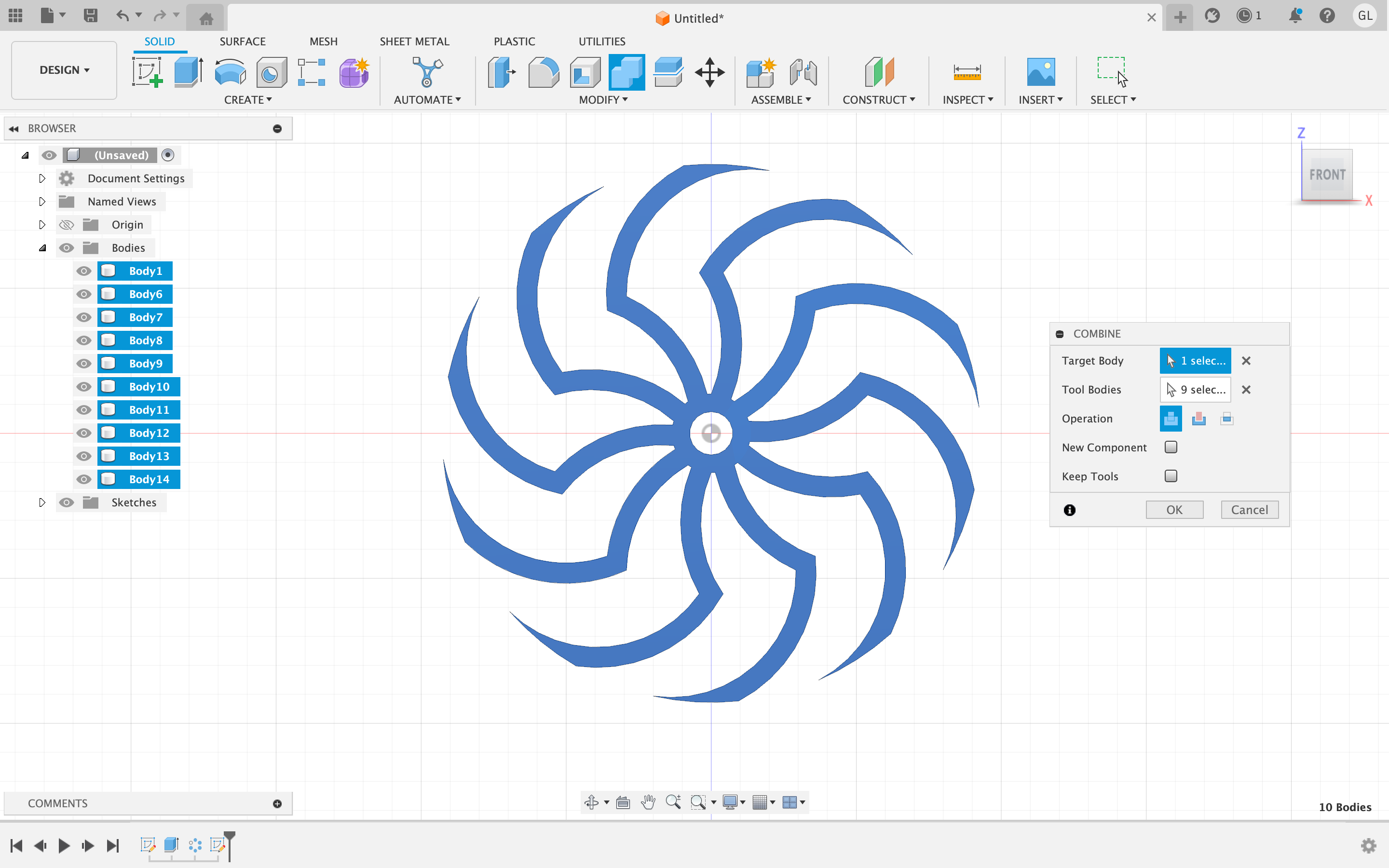
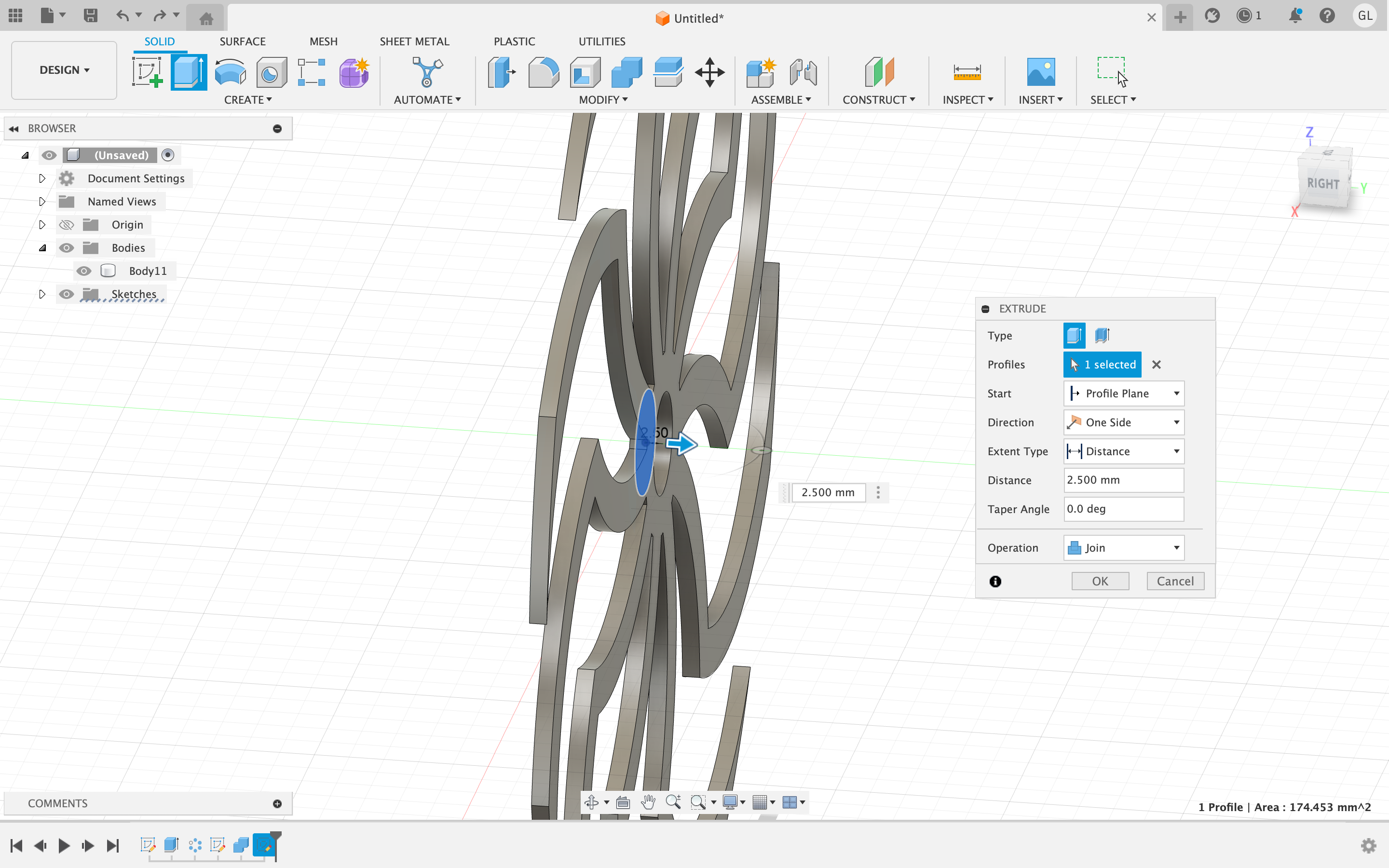
To create the shape, I started by designing a 2D hand shape. Using Fusion 360, I utilized the circular pattern tool to replicate the hand shape around the center, creating a total of 10 hands. After completing the duplication process, I employed the combine tool to merge all of these individual hand shapes into a single cohesive shape.
Laser Cutting Phase:
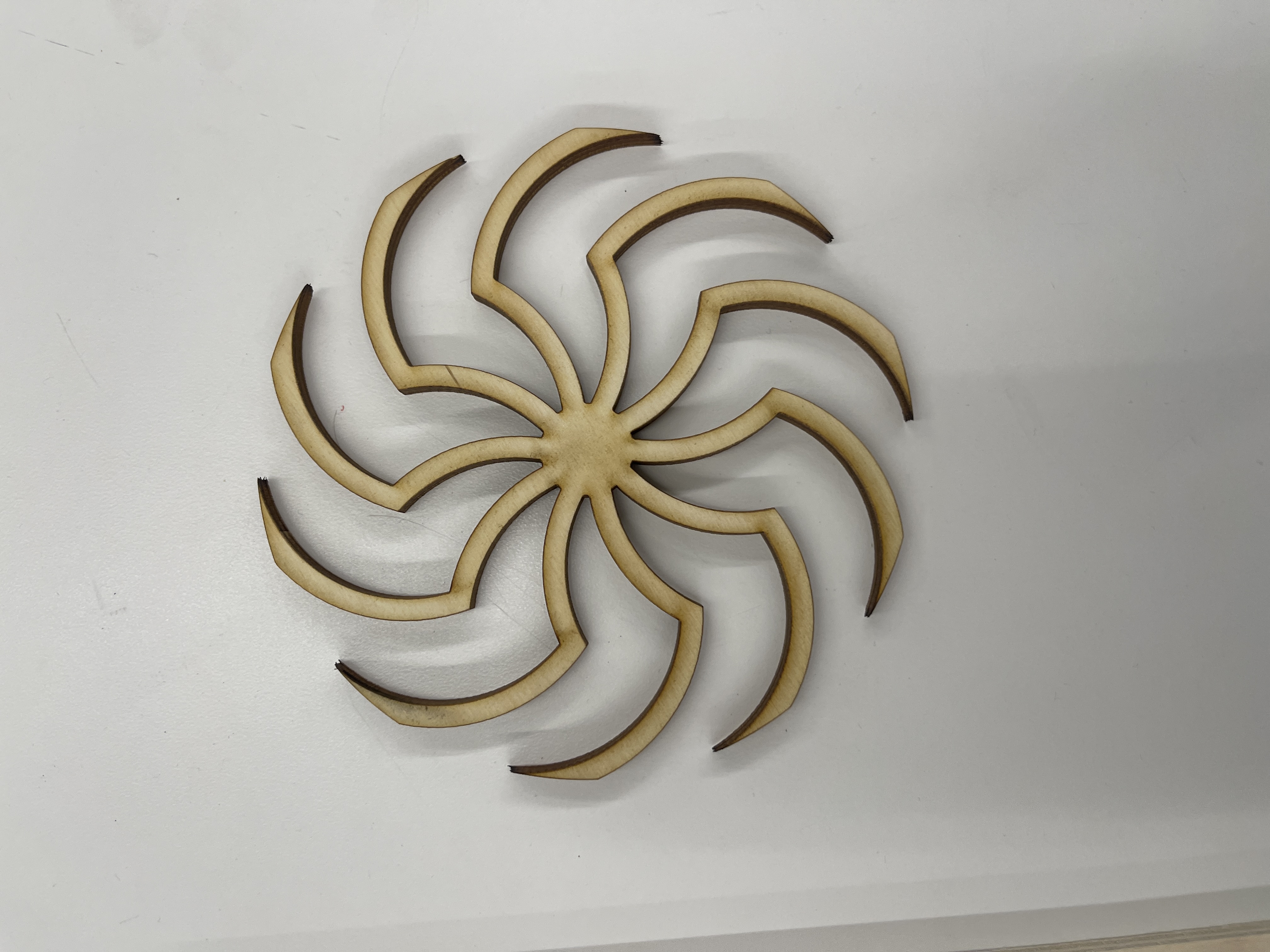
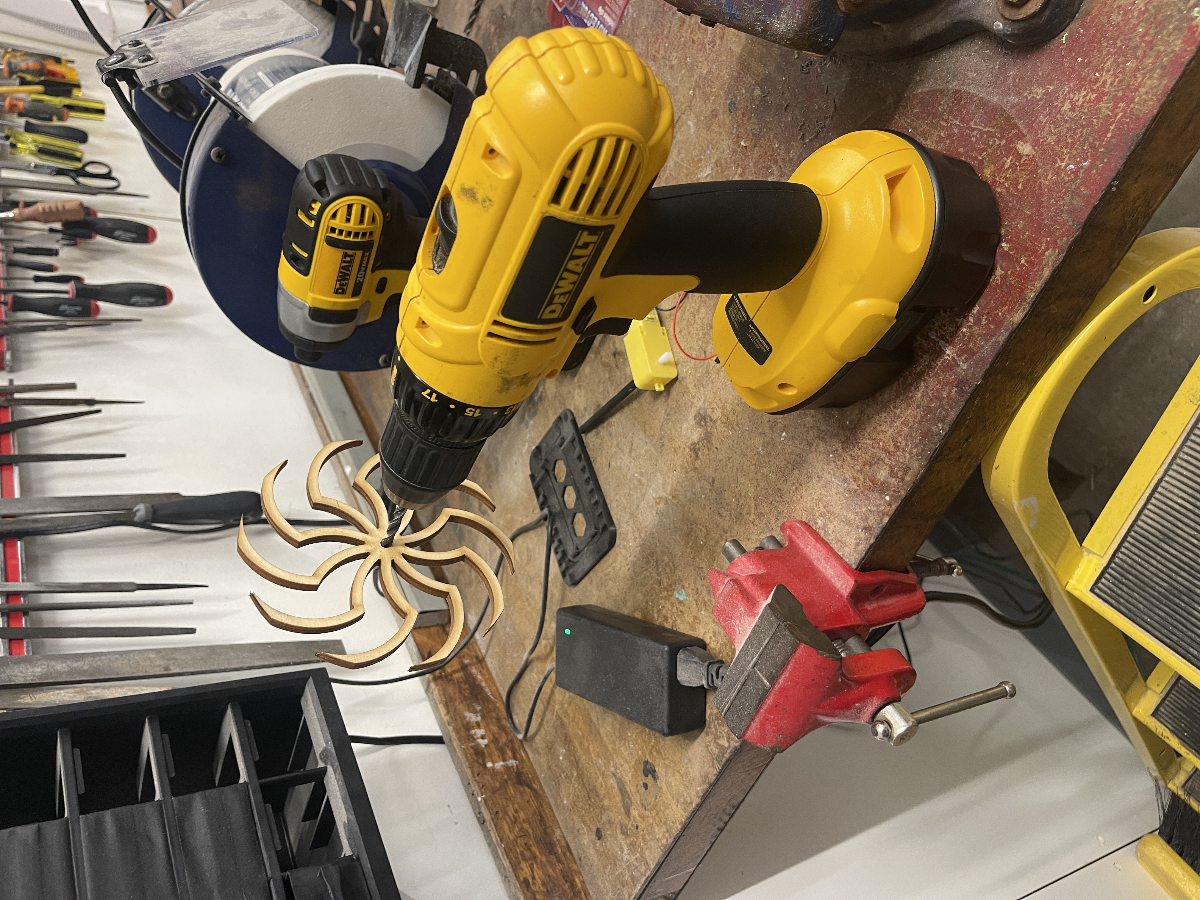
After designing the 2D model of the shape, I implemented this onto the laser cutter using a medium of plywood. I also then used a hand drill to create a small hole (with the same size as the wooden rod) in the center of the shape.
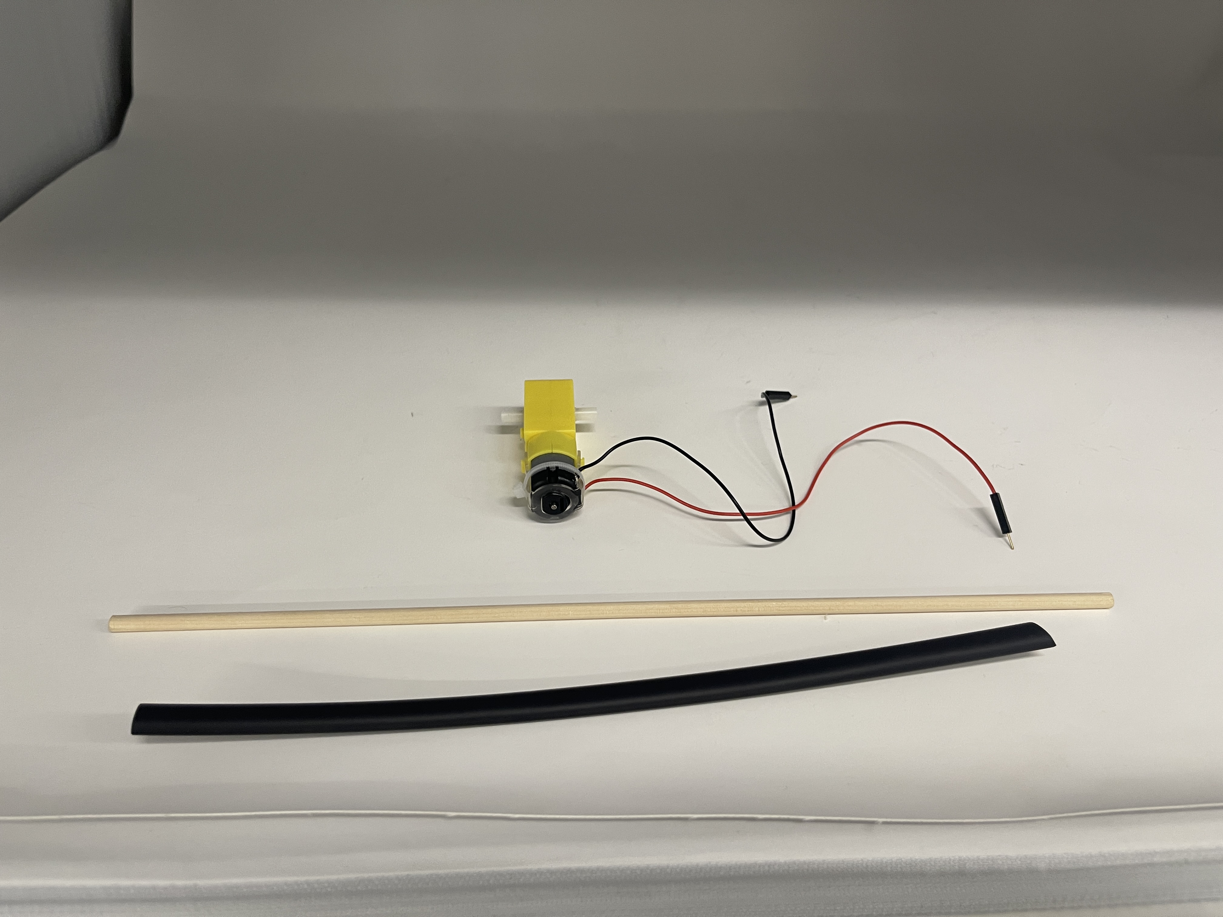
Furthermore, I also attached a wooden rod to the end of one of the axles on the motor. This was because the motor's original axle was too short to fully fit through the hole of the shape that I designed. Using a heat shrink tube, I connected a wooden rod to the end of one of the motors.
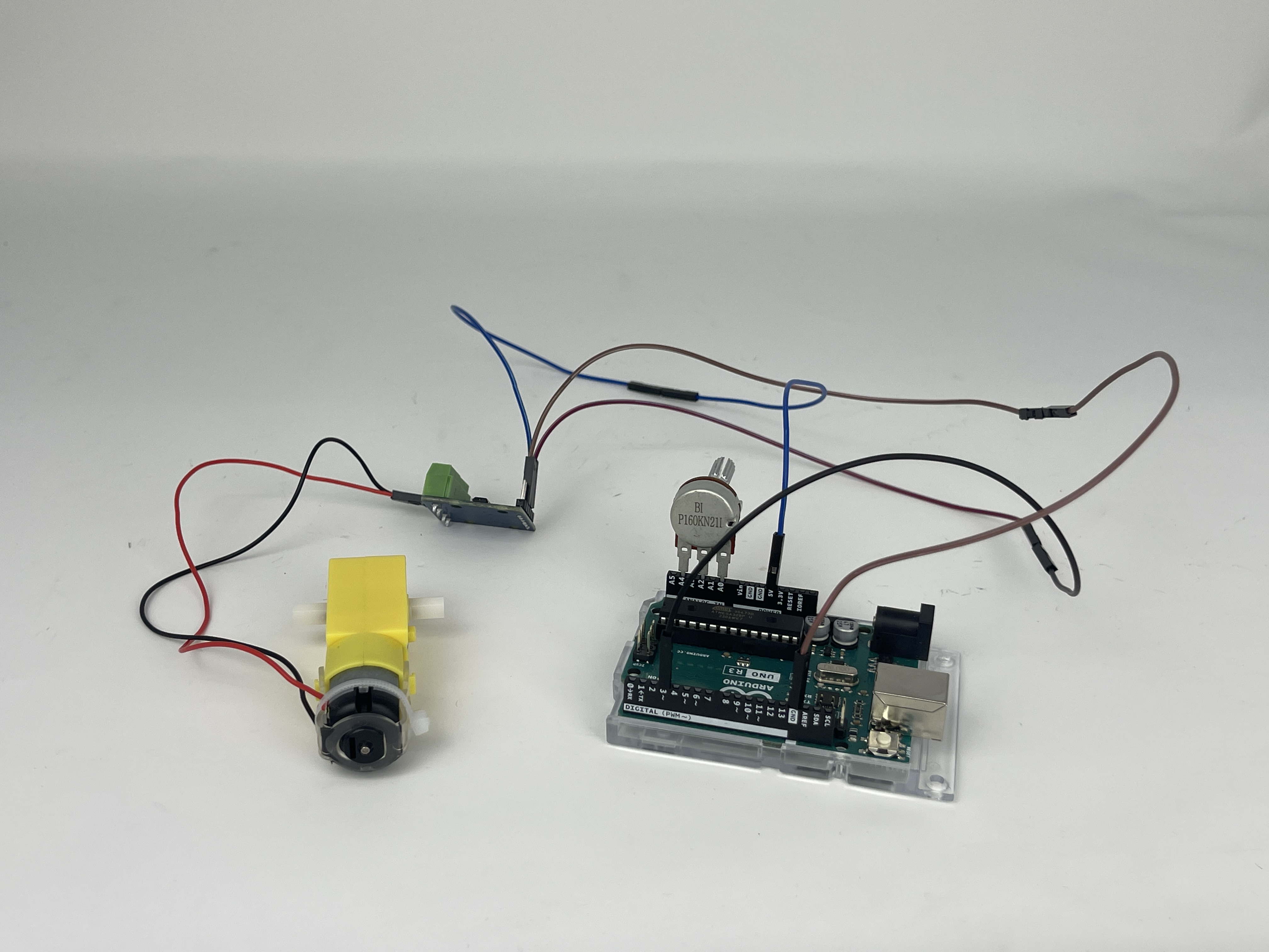
The next step was to create a running motor which would have an axle that would go through the hole of the shape. Using an arduino (micro-controller), I programmed a sequence which would use a potentiometer to control the speed of a specific motor. Above is a picture of my setup and below the Arduino code I used to control the potentiometer and the motor.
                /*
                   Code to run motor in one direction based on potentiometer reading.
                   Motor driver speed control on pin 3 (direction LOW by default).
                   Potentiometer plugged into A0, A2, and A4 on Arduino Uno (or similar).
                */

                // Setup function runs once when the Arduino is powered on or reset
                void setup() {
                  // Set pin modes for motor control and potentiometer connections
                  pinMode(3, OUTPUT);        // Motor driver speed control pin
                  pinMode(A0, OUTPUT);       // GND connection for the potentiometer
                  pinMode(A4, OUTPUT);       // 3.3V connection for the potentiometer

                  // Set initial states for potentiometer connections
                  digitalWrite(A0, LOW);     // Set GND to LOW
                  digitalWrite(A4, HIGH);    // Set 3.3V to HIGH
                }

                // Loop function continuously runs after the setup function
                void loop() {
                  // Read the potentiometer value from the wiper on A2
                  int pot_value = analogRead(A2);

                  // Map the potentiometer value to the motor speed range (0-255)
                  int motor_speed = map(pot_value, 0, 1023, 255, 0);

                  // Set the motor speed using PWM on pin 3
                  analogWrite(3, motor_speed);

                  // Small delay to stabilize motor speed
                  delay(1);
                }
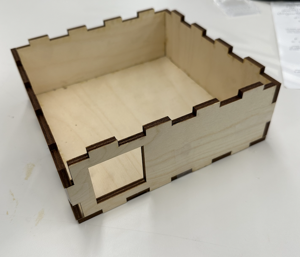
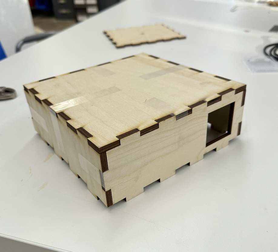
After completing the rotating object, I needed to create a structural base for the kinetic sculpture. What I initially planned was to create a box that would hold all of the components of the sculpture in place. Thus, with my knowledge in press-fit models, I constructed a box on Fusion360, and printed it out. Here is how it came out:
Final Product:
Here is my Kinetic Sculpture running at different speeds (adjusted by the use of the potentiometer)
Final Thoughts:
I believe that this assignment turned out pretty successfully. I managed to create the kinetic scultpure and implement the use of the Arduino and micro-controller programming, to control the speed of the motor. However, one limitation of this product would have been the structure that I created to hold the spinning shape in place. I could have created a compartment that held all of the components of the kinetic scultpure, but also hides the Arduino and the wires. Furthermore, I had some problems trying to get a second stationary shape in the sculpture, in order to fully replicate the model that I used as inspiration for this.