vision:
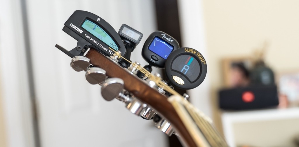
One of my personal passions include playing musical instruments such as the guitar. I wanted to create a simple device/mechanism that would support guitar players, so I found one specific problem that all players struggle with: tuning. Being a passioniate guitar player, I realize and understand the frustration that some guitar players experience while trying to manually tune the six strings on a guitar. Therefore, through this final project, I have decided to develop a device that not only simplifies, but automates this entire process.
Final Demo Video:
Initial Plan:
the automatic guitar tuner will consist of two main components:
Input: the frequencies of the guitar strings recorded with a microphone
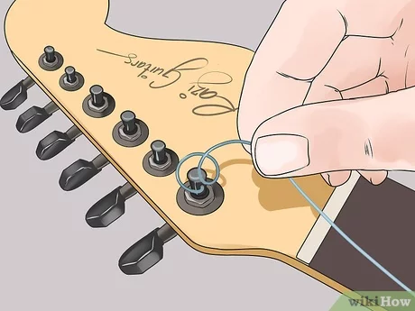
Output: the adjustment of the pegs to change the tune of the guitar strings
Updated Plan:
After careful thought and consideration, I decided to simplify this entire process. The primary reason for this was because it was challenging to get a mechanism/device that could produce enough torque to turn the pegs on a real guitar.
Therefore, in order to make the project more manageable, I decided to create a musicbox that emits the precise frequency of each individual guitar string. This device will allow a user to tune their guitar manually, aligning it perfectly with the needed frequencies. By doing so, each string will be attuned to the exact pitch required for optimal performance.
Fabrication Process
Electronics Phase (Software and Circuitry):
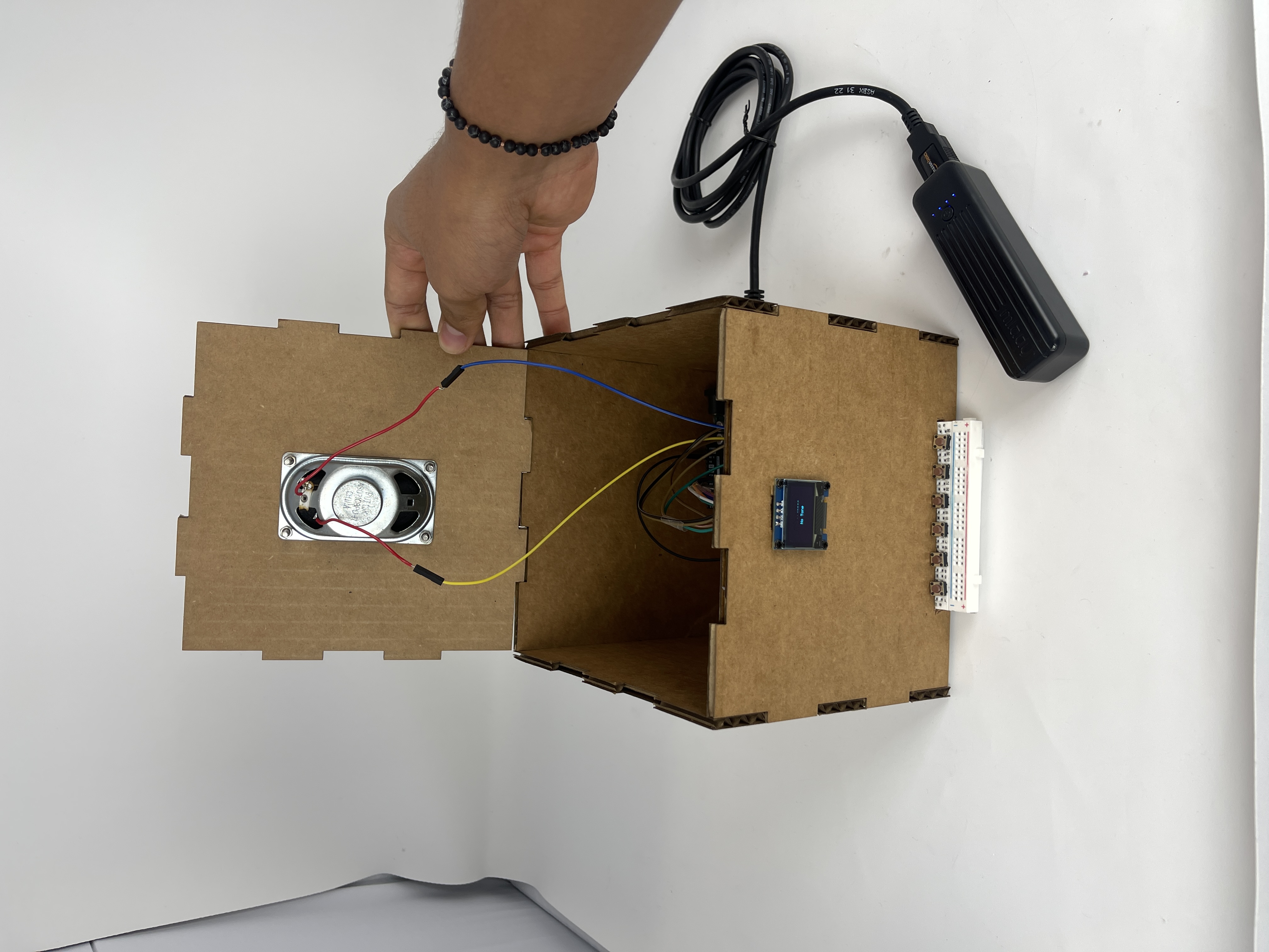
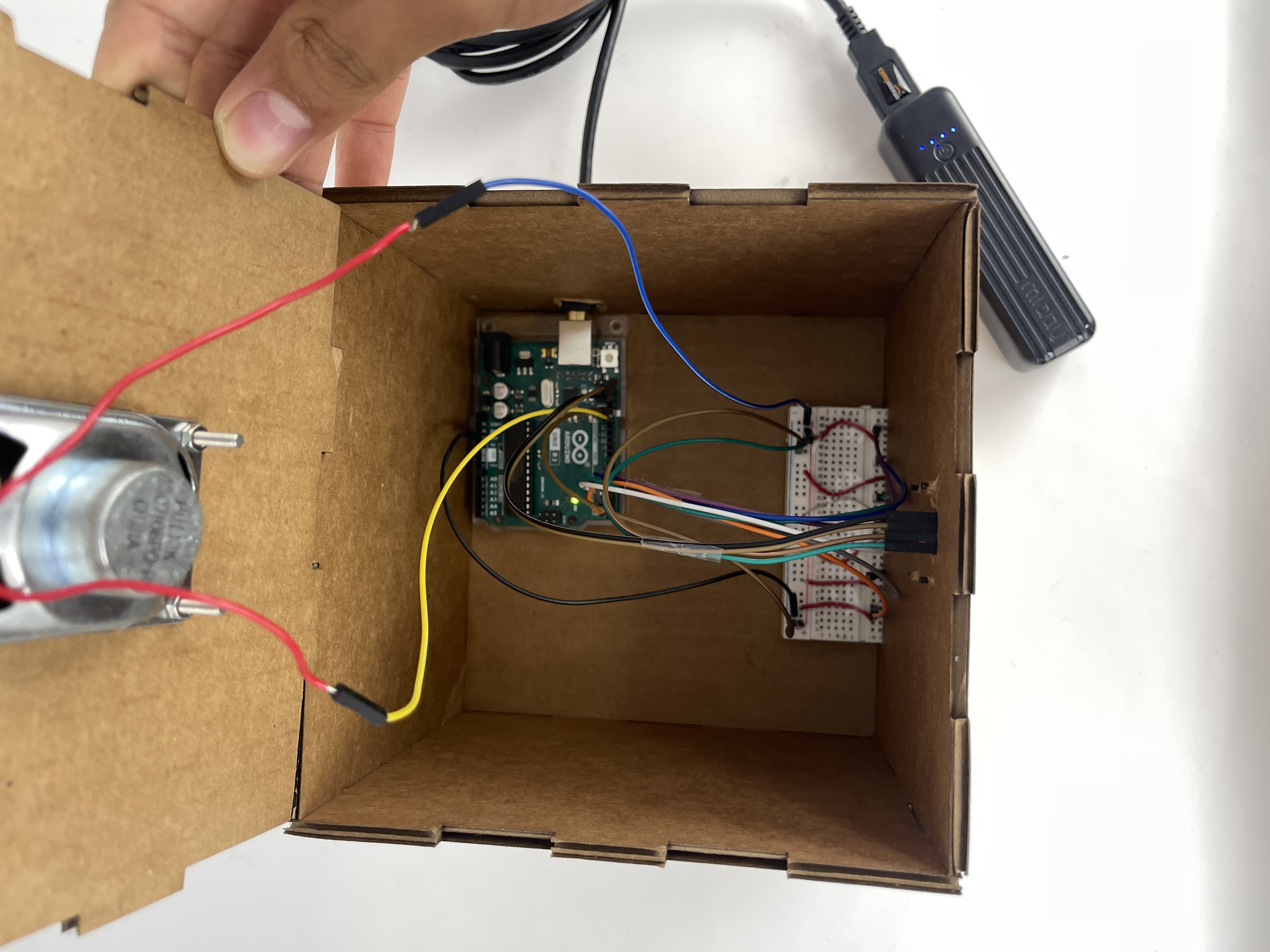
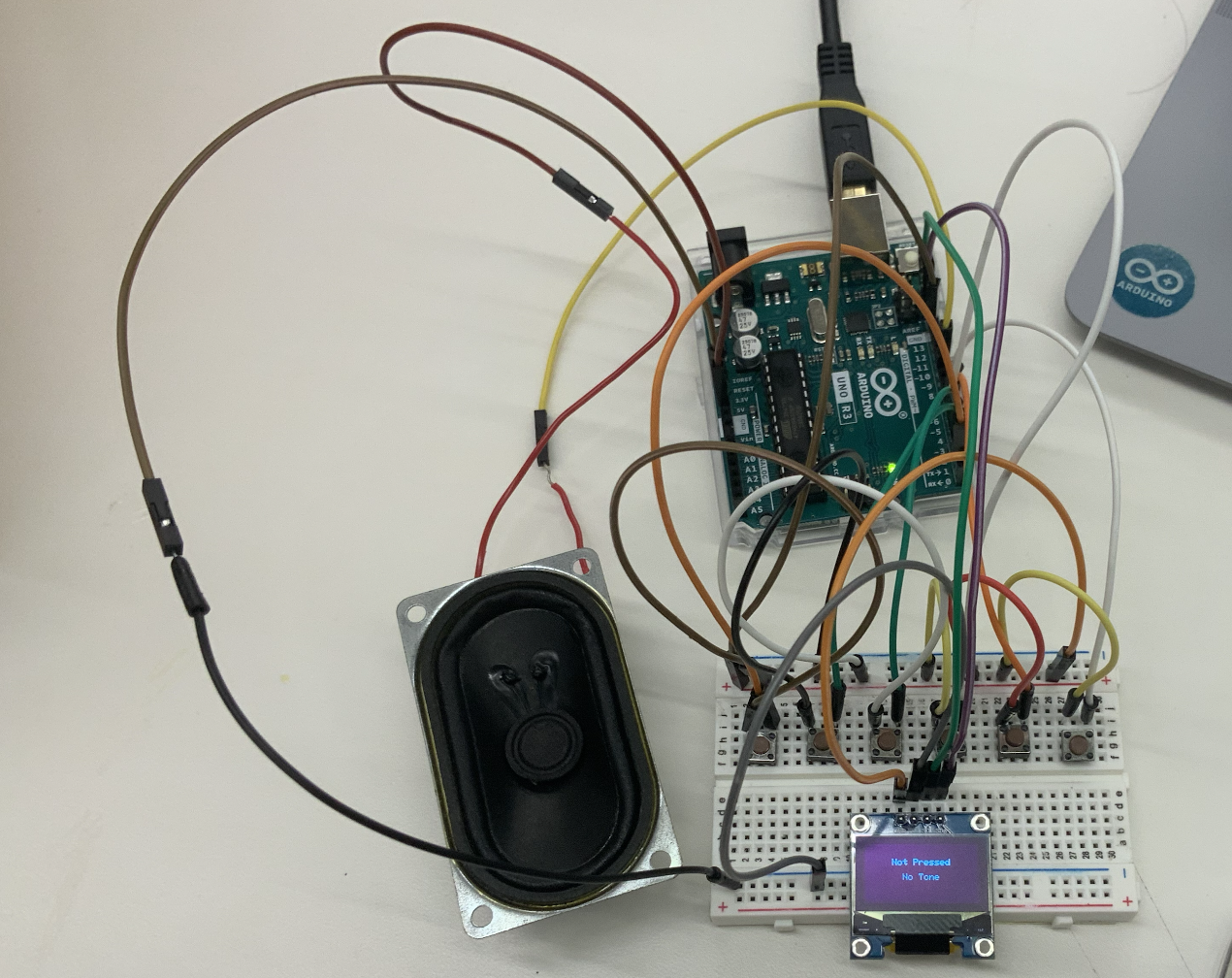
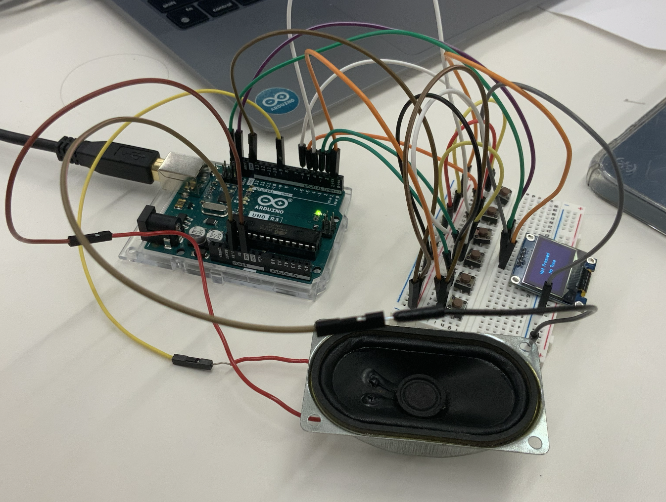
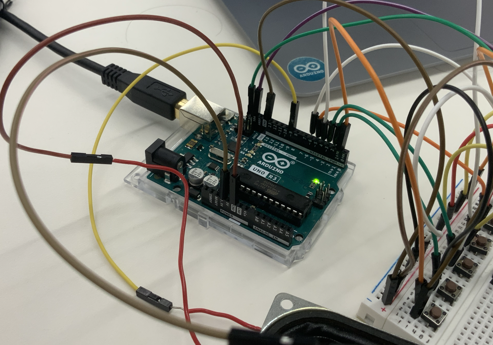
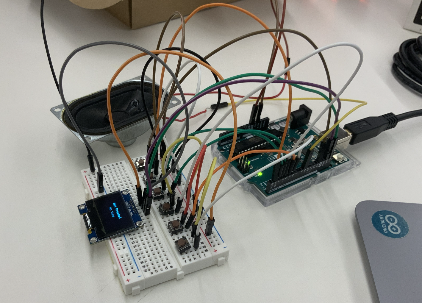
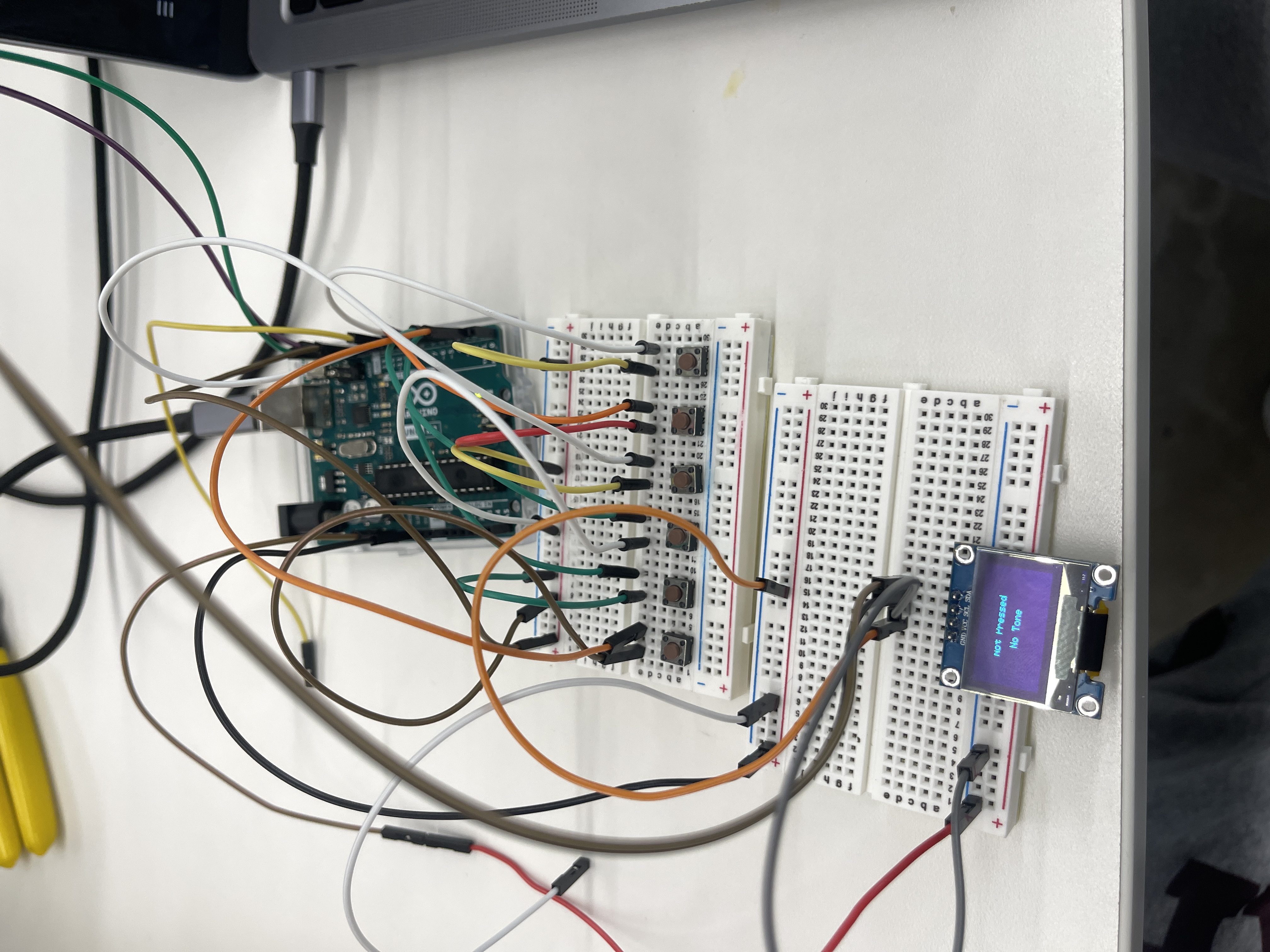
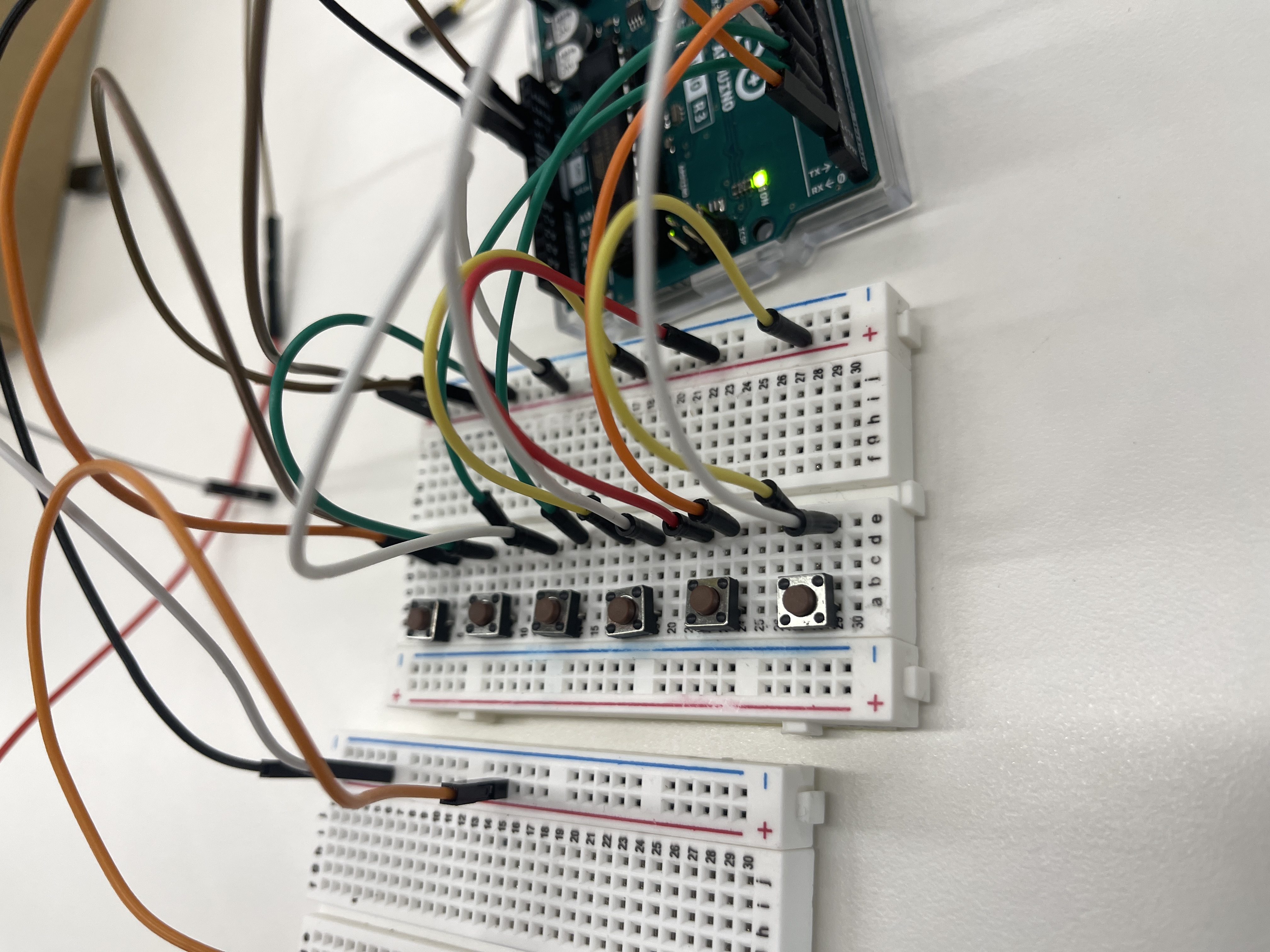
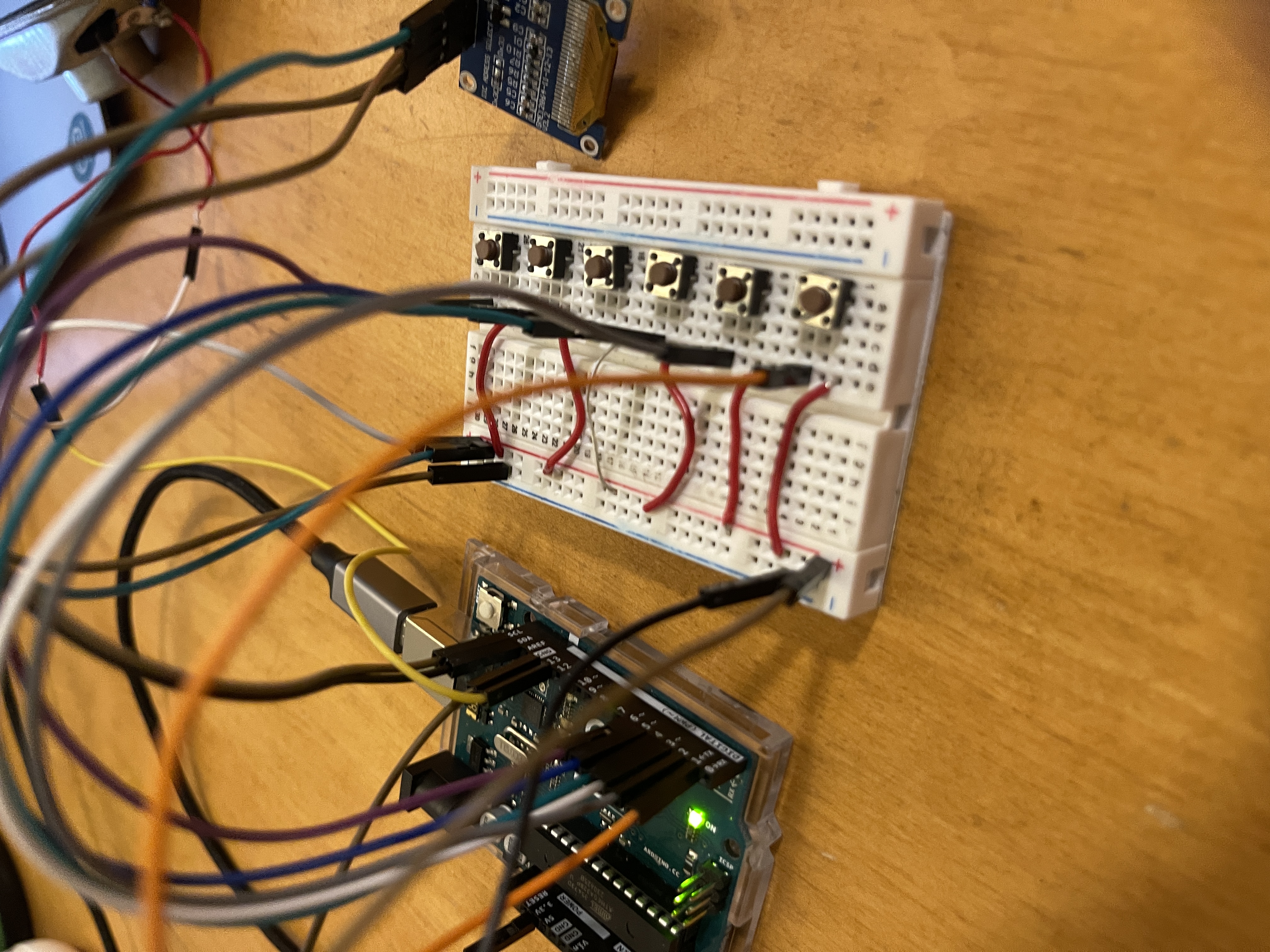
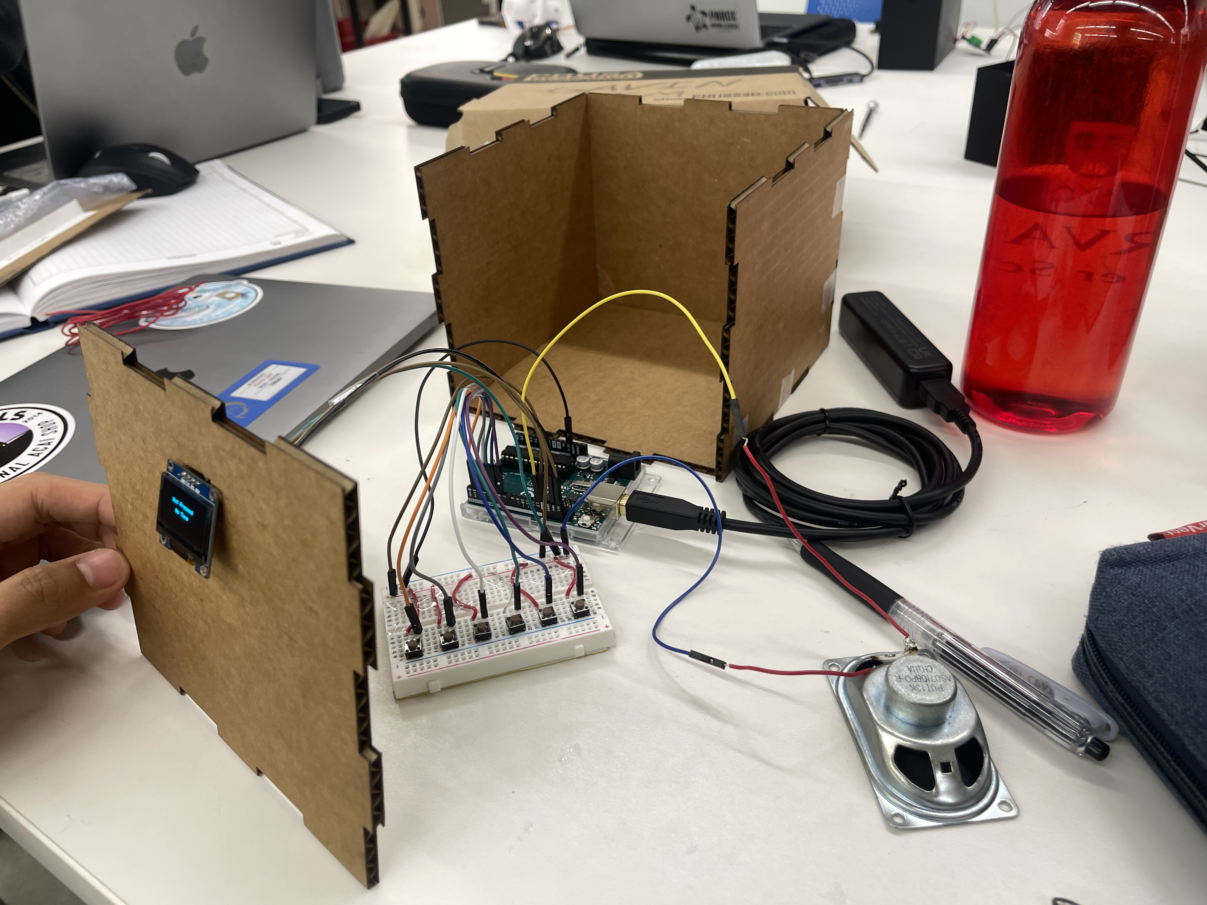
To get a start in this project, I first designed a circuit using the Arduino Uno Microcontroller, that represents a musicbox which can emulate the different frequencies of a guitar. Within this system, the user is able to press 6 different buttons (which correlate to the 6 different strings on a guitar), which each triggers a distinct sound frequency. These different sound frequencies, which represent the 6 different guitar strings, are produced through a speaker which is also connected to the Arduino Uno. Furthermore, this system also provides visual cues; each button corresponds to a unique text displayed on the OLED screen, creating a more multifaceted user experience.
Here are a few pictures of the inital setup:
Here is a list of the equipment that I used:
Here is the code that I created to use for this:
                #include <Wire.h>
                #include <Adafruit_GFX.h>
                #include <Adafruit_SSD1306.h>

                #define SCREEN_WIDTH 128 // OLED display width, in pixels
                #define SCREEN_HEIGHT 64 // OLED display height, in pixels

                // Declaration for an SSD1306 display connected to I2C (SDA, SCL pins)
                #define OLED_RESET -1 // Reset pin # (or -1 if sharing Arduino reset pin)
                Adafruit_SSD1306 display(SCREEN_WIDTH, SCREEN_HEIGHT, &Wire, OLED_RESET);

                const int buttonPins[] = {1, 2, 3, 4, 5, 6}; // Buttons connected to digital pins
                const int speakerPin = 9; // Speaker connected to digital pin 9

                // Frequencies for E2, A2, D3, G3, B3, E4
                const int toneFrequencies[] = {82, 110, 147, 196, 247, 330};

                String getNote(int index) {
                    const String notes[] = {"E2", "A2", "D3", "G3", "B3", "E4"};
                    if (index >= 0 && index < sizeof(buttonPins)/sizeof(int)) {
                        return notes[index];
                    }
                    return "Unknown";
                }

                String getString(int index) {
                    if (index >= 0 && index < sizeof(buttonPins)/sizeof(int)) {
                        return "String " + String(index + 1);
                    }
                    return "Unknown";
                }

                void setup() {
                    for (int i = 0; i < sizeof(buttonPins)/sizeof(int); i++) {
                        pinMode(buttonPins[i], INPUT_PULLUP); // Initialize the button pin as input with internal pull-up resistor
                    }
                    pinMode(speakerPin, OUTPUT); // Initialize the speaker pin as an output

                    // SSD1306_SWITCHCAPVCC = generate display voltage from 3.3V internally
                    if(!display.begin(SSD1306_SWITCHCAPVCC, 0x3C)) { // Address 0x3C for 128x64
                        Serial.println(F("SSD1306 allocation failed"));
                        for(;;); // Don't proceed, loop forever
                    }
                    display.clearDisplay();
                    display.setTextSize(1); // Set text size
                    display.setTextColor(SSD1306_WHITE);
                }

                void loop() {
                    display.clearDisplay();
                    bool buttonPressed = false;

                    for (int i = 0; i < sizeof(buttonPins)/sizeof(int); i++) {
                        int buttonState = digitalRead(buttonPins[i]); // Read the state of the button
                        if (buttonState == LOW) { // If the button is pressed (LOW because of pull-up resistor)
                            tone(speakerPin, toneFrequencies[i]); // Play a tone on the speaker
                            String note = getNote(i);
                            String stringNum = getString(i);
                            display.setCursor((SCREEN_WIDTH - (7 * 6))/2, 16); // 6 is approximate width of one character
                            display.println("Pressed");
                            display.setCursor((SCREEN_WIDTH - (note.length() + stringNum.length() + 2) * 6)/2, 32); // 6 is approximate width of one character
                            display.print(note);
                            display.print(", ");
                            display.println(stringNum);
                            buttonPressed = true;
                            break; // only one button can be pressed at a time
                        }
                    }

                    if (!buttonPressed) {
                        noTone(speakerPin); // If no button is pressed, stop playing the tone
                        display.setCursor((SCREEN_WIDTH - (11 * 6))/2, 16); // 6 is approximate width of one character
                        display.println("Not Pressed");
                        display.setCursor((SCREEN_WIDTH - (7 * 6))/2, 32); // 6 is approximate width of one character
                        display.println("No Tone");
                    }

                    display.display();
                }
Here are some videos of the inital setup working:
Once I established the foundational circuit which incorporated all of the essential components, I decided to recreate the circuitry but with a neater and more efficient layout. I did this by incorporating an additional breadboard into the system, which provided extra space for better wiring.
Additionally, after creating a base circuit, I tried to experiment with other input/output devices that could potentially make my final product better. For instance, I tried to experiment with a bigger display (LCD), rather than the OLED. Furthermore, I also tried to implement the use of a microphone to potentially create the initial guitar tuner that I intended to make.
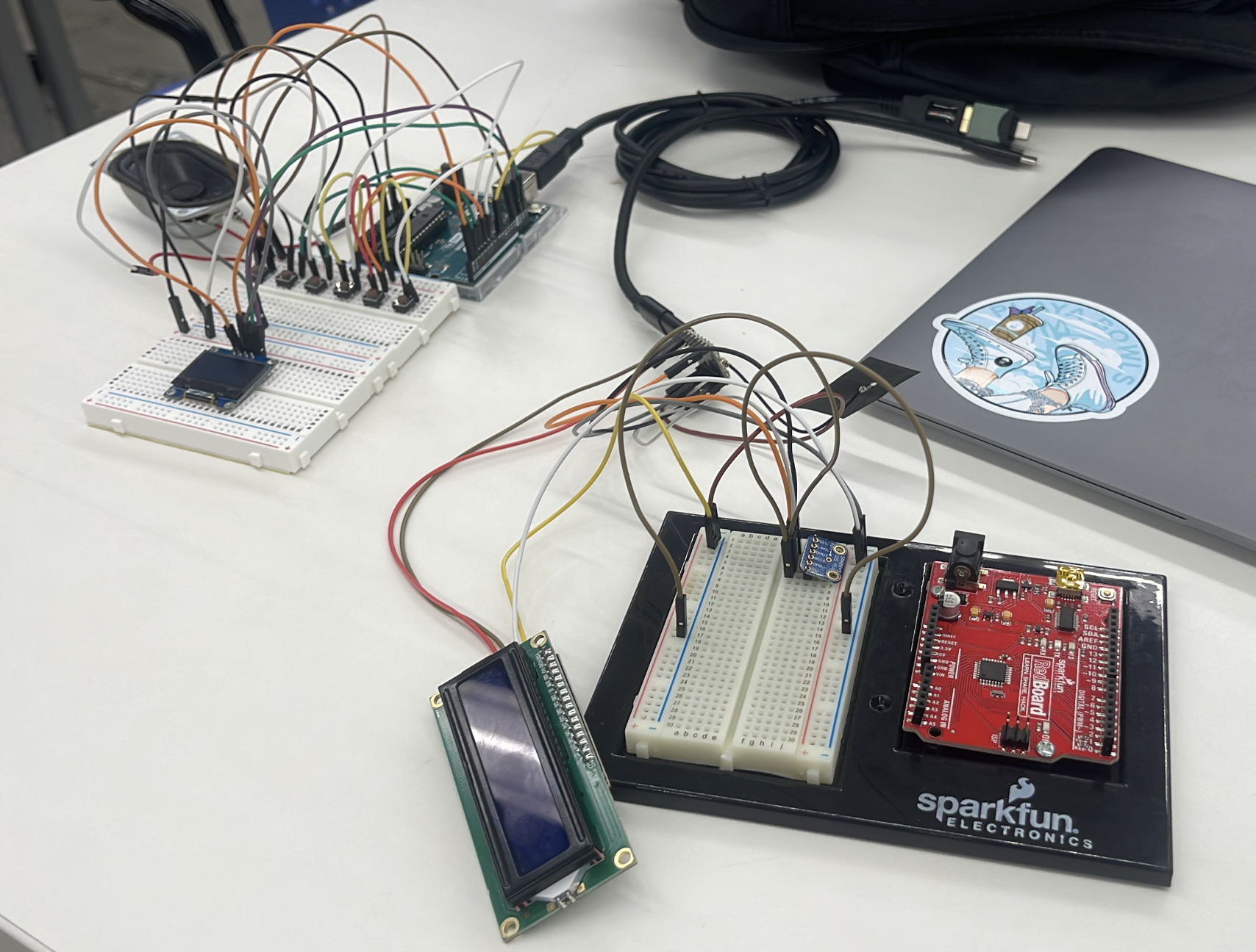
However, through this experimentation, I realized that it was a struggle to get these components to work. For example, I was having troubles with receiving a frequnecy from the microphone. In addition, I figured that using the OLED screen was a better option that the LCD Display. Although the LCD provided a larger screen, I found that the OLED screen was more aesthetically pleasing to the eye; which is why I decided to keep it in my final project.
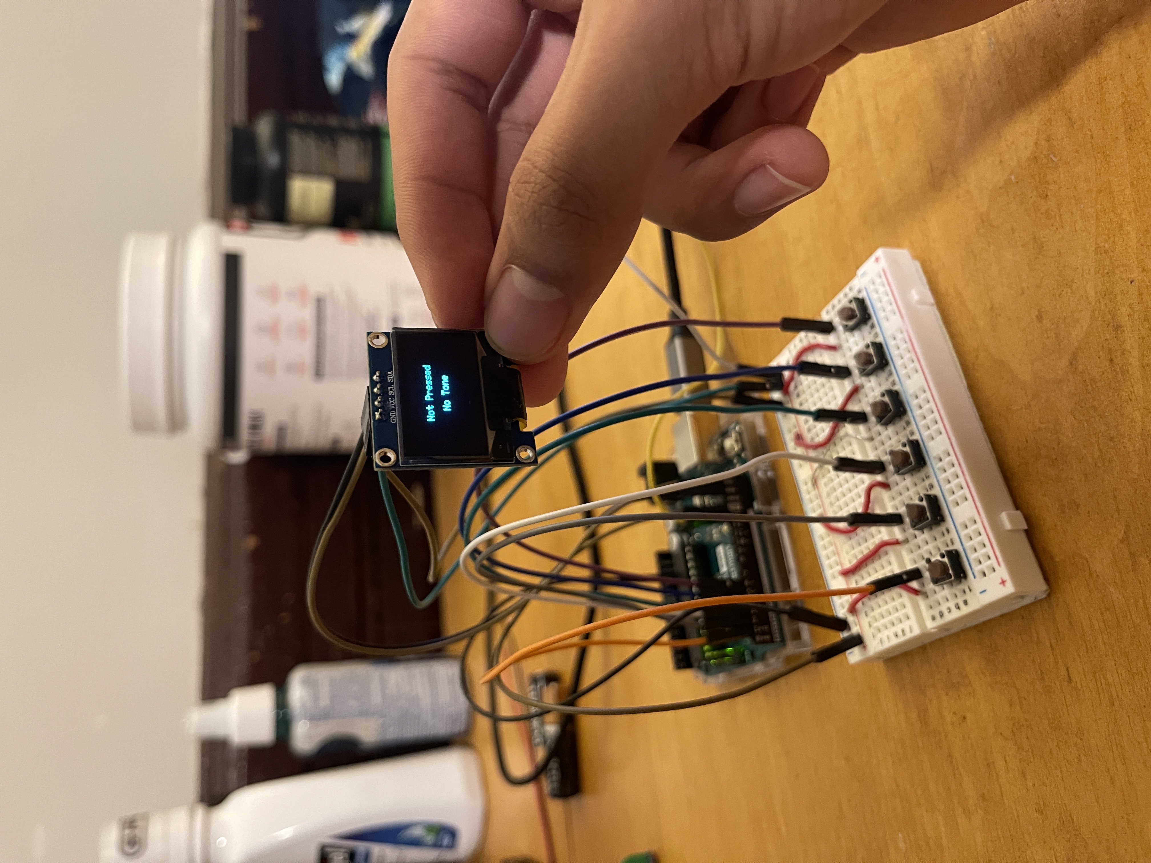
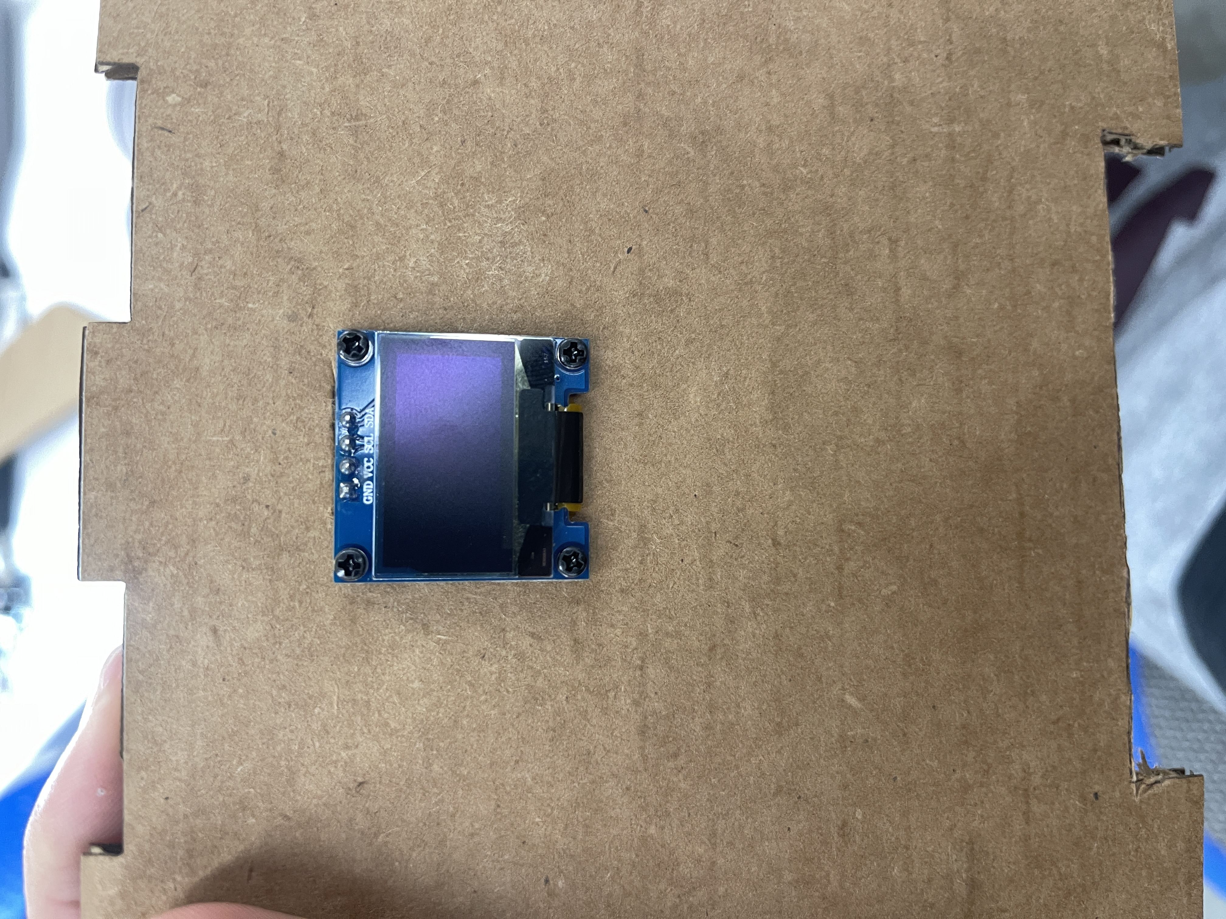
After remaking the circuit, I made the decision to remove the additional breadboard, to keep the sort-of compact design for the system. I then remade the circuit and made it even more neater, using wires that stick directly to the breadboard without causing any additional blockage. Furthermore, I attached the OLED display using wires instead of just sticking it directly into the breadboard.
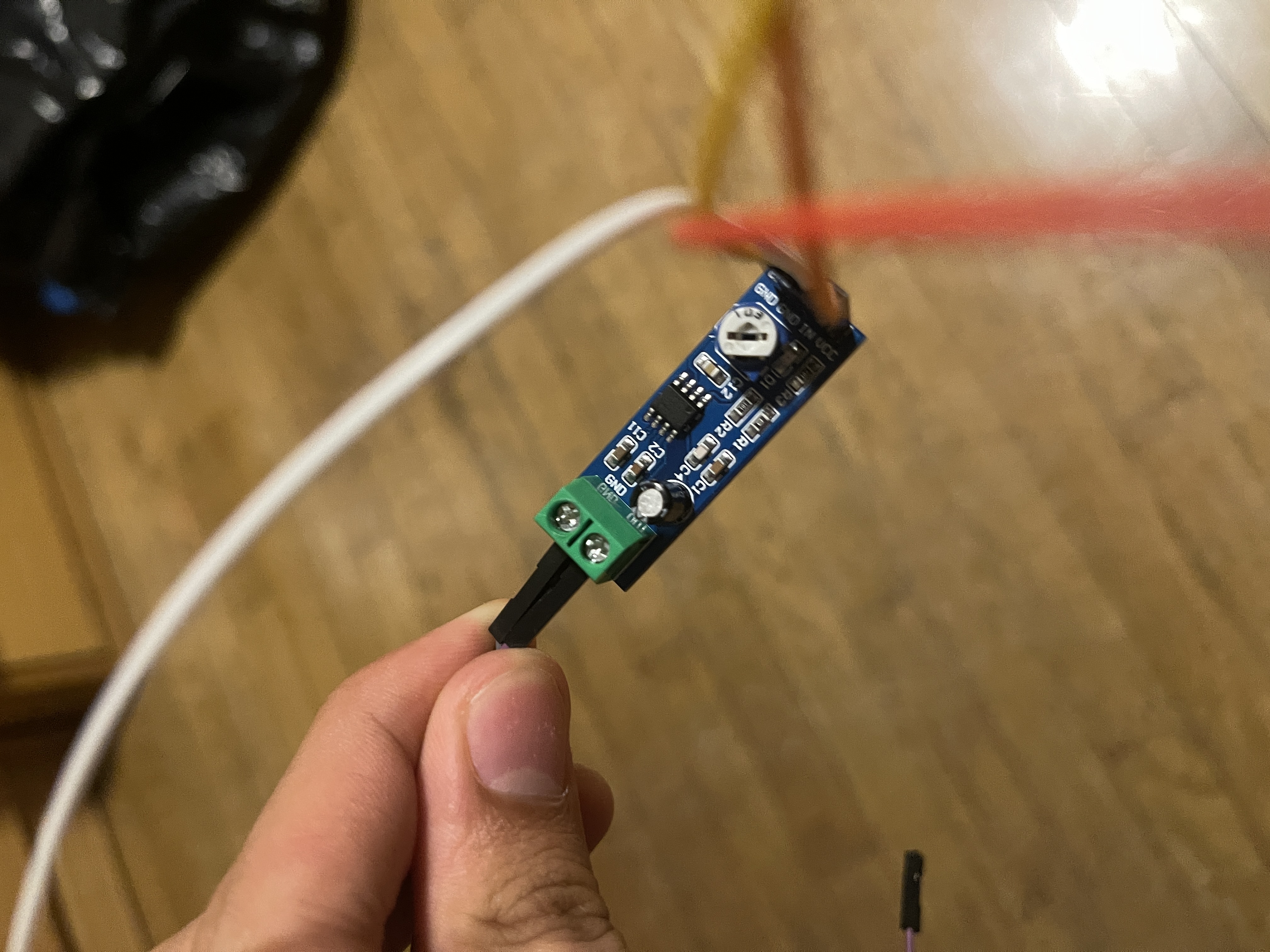
I then attempted to attach an amplifier to the system, in order to make the sound of the speaker a little louder. However, I found this step unsuccessful, as I found troubles with using the amplifier to alter the volume of the speaker.
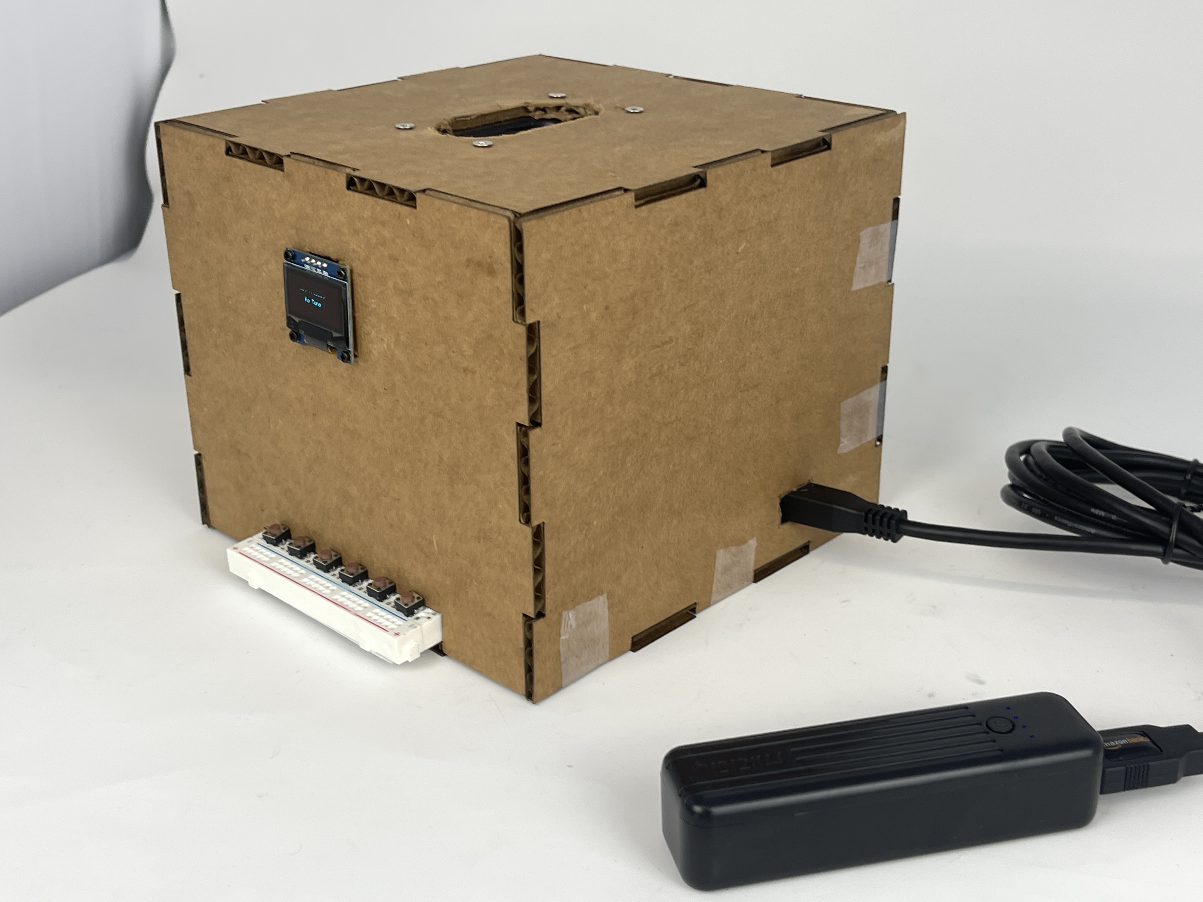
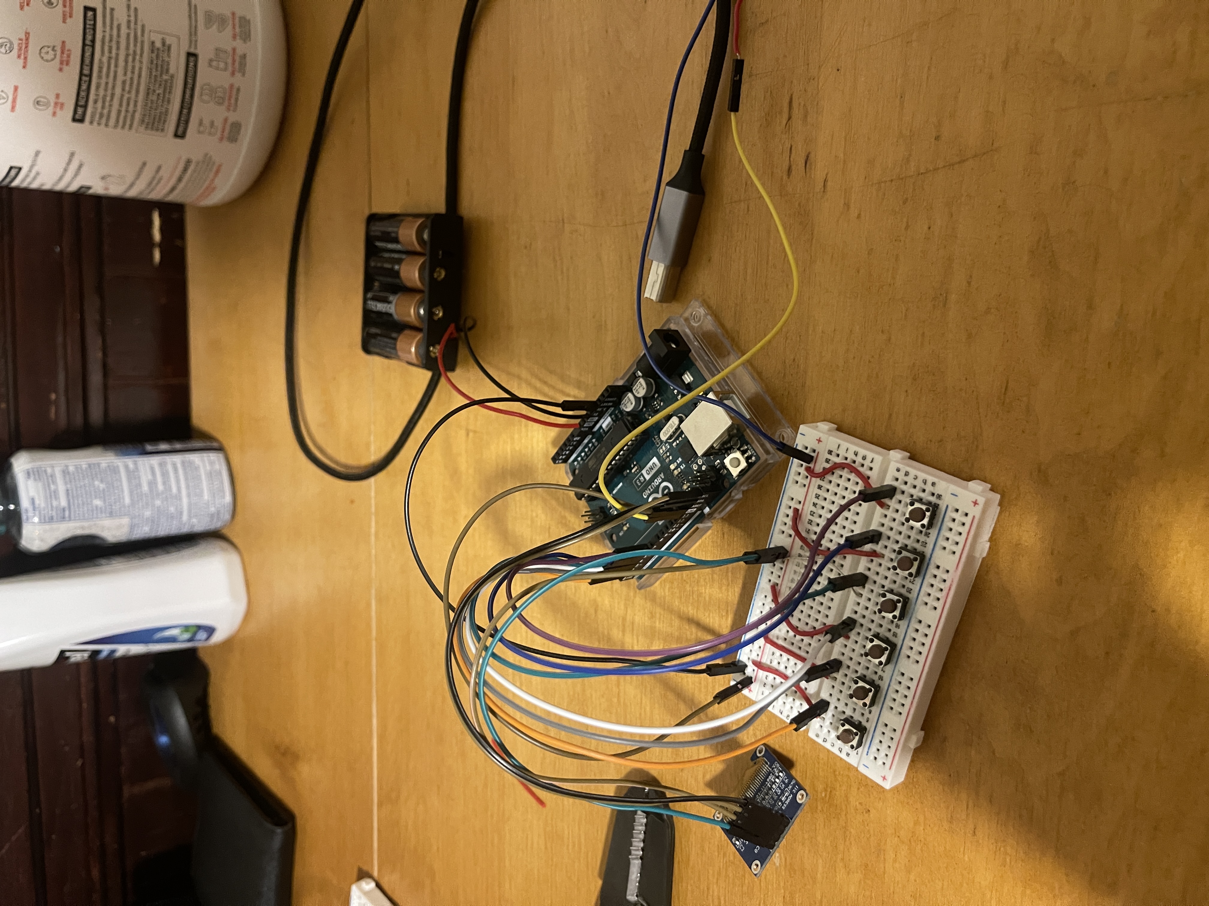
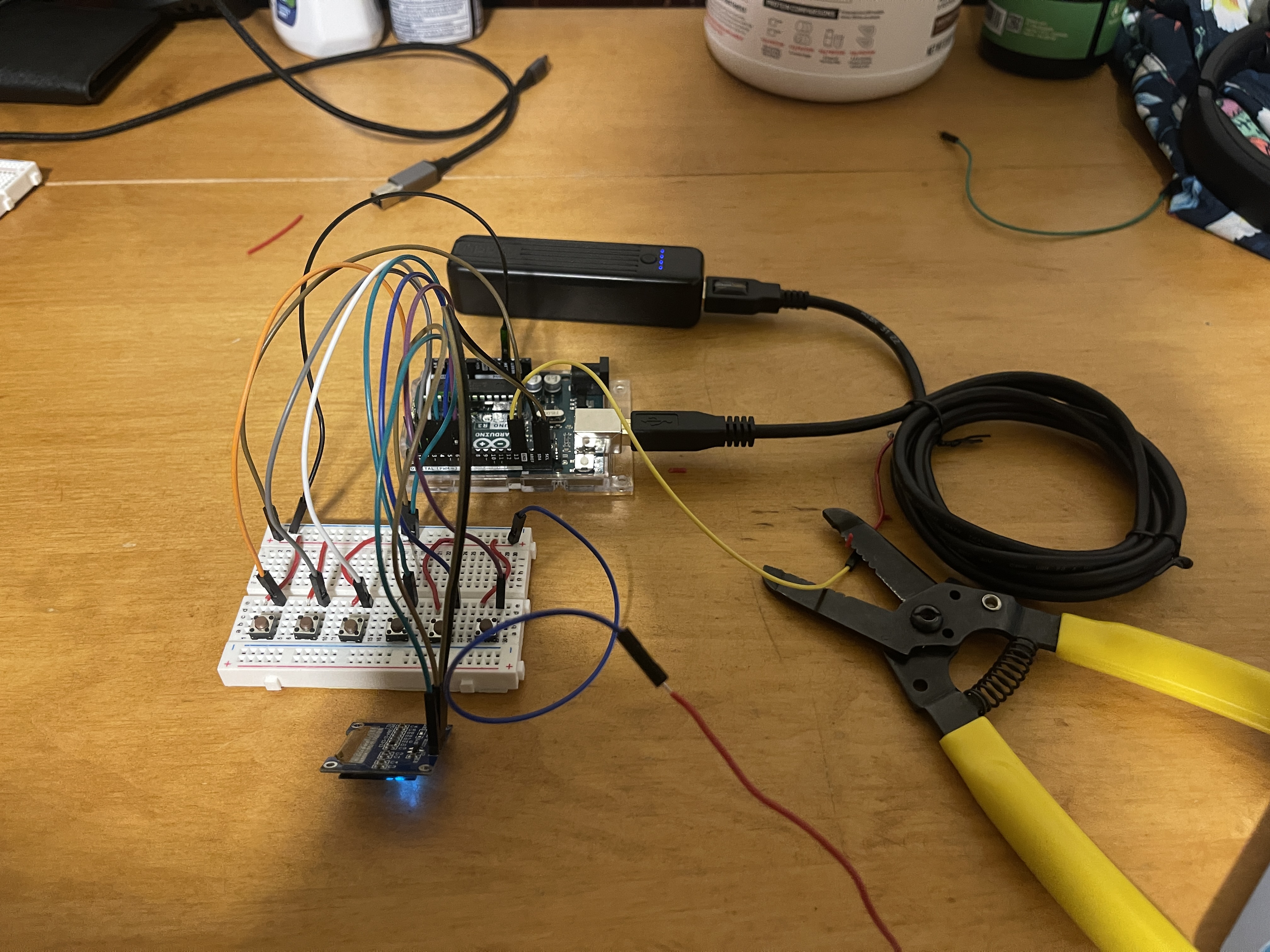
After unsuccessfully trying to implement the use of an amplifier within my system, I eventually thought about making this device portable, and easy to carry around. Thus, I experimented with both the use of Double AA Batteries and a Powerbank to powerup the Arduino Uno Microcontroller.
Here is my final completed code that I used for this project:
                #include
                #include
                #include

                #define SCREEN_WIDTH 128 // OLED display width, in pixels
                #define SCREEN_HEIGHT 64 // OLED display height, in pixels

                // Declaration for an SSD1306 display connected to I2C (SDA, SCL pins)
                #define OLED_RESET -1 // Reset pin # (or -1 if sharing Arduino reset pin)
                Adafruit_SSD1306 display(SCREEN_WIDTH, SCREEN_HEIGHT, &Wire, OLED_RESET);

                const int buttonPins[] = {1, 2, 3, 4, 5, 6}; // Buttons connected to digital pins
                const int speakerPin = 13; // Speaker connected to digital pin 9


                // Frequencies for E2, A2, D3, G3, B3, E4
                const int toneFrequencies[] = {82, 110, 147, 196, 247, 330};


                String getNote(int index) {
                const String notes[] = {"E2", "A2", "D3", "G3", "B3", "E4"};
                if (index >= 0 && index < sizeof(buttonPins)/sizeof(int)) {
                return notes[index];
                }
                return "Unknown";
                }


                String getString(int index) {
                if (index >= 0 && index < sizeof(buttonPins)/sizeof(int)) {
                return "String " + String(index + 1);
                }
                return "Unknown";
                }


                void setup() {
                for (int i = 0; i < sizeof(buttonPins)/sizeof(int); i++) {
                pinMode(buttonPins[i], INPUT_PULLUP); // Initialize the button pin as input with internal pull-up resistor
                }
                pinMode(speakerPin, OUTPUT); // Initialize the speaker pin as an output


                // SSD1306_SWITCHCAPVCC = generate display voltage from 3.3V internally
                if(!display.begin(SSD1306_SWITCHCAPVCC, 0x3C)) { // Address 0x3C for 128x64
                Serial.println(F("SSD1306 allocation failed"));
                for(;;); // Don't proceed, loop forever
                }
                display.clearDisplay();
                display.setTextSize(1); // Set text size
                display.setTextColor(SSD1306_WHITE);
                }


                void loop() {
                display.clearDisplay();
                bool buttonPressed = false;


                for (int i = 0; i < sizeof(buttonPins)/sizeof(int); i++) {
                int buttonState = digitalRead(buttonPins[i]); // Read the state of the button
                if (buttonState == LOW) { // If the button is pressed (LOW because of pull-up resistor)
                tone(speakerPin, toneFrequencies[i]); // Play a tone on the speaker
                String note = getNote(i);
                String stringNum = getString(i);
                for (int j = 0; j < 10; j++) {
                display.clearDisplay();
                display.setCursor((SCREEN_WIDTH - (7 * 6))/2, 16); // 6 is approximate width of one character
                display.println("Pressed");
                display.setCursor((SCREEN_WIDTH - (note.length() + stringNum.length() + 2) * 6)/2, 32); // 6 is approximate width of one character
                display.print(note);
                display.print(", ");
                display.println(stringNum);
                display.display();
                delay(100); // You might need to adjust this delay
                }


                buttonPressed = true;
                break; // only one button can be pressed at a time
                }
                }


                if (!buttonPressed) {
                noTone(speakerPin); // If no button is pressed, stop playing the tone
                display.setCursor((SCREEN_WIDTH - (11 * 6))/2, 16); // 6 is approximate width of one character
                display.println("Not Pressed");
                display.setCursor((SCREEN_WIDTH - (7 * 6))/2, 32); // 6 is approximate width of one character
                display.println("No Tone");
                }


                display.display();
                }
Assembly Phase (CAD Software and PrusaSlicer):
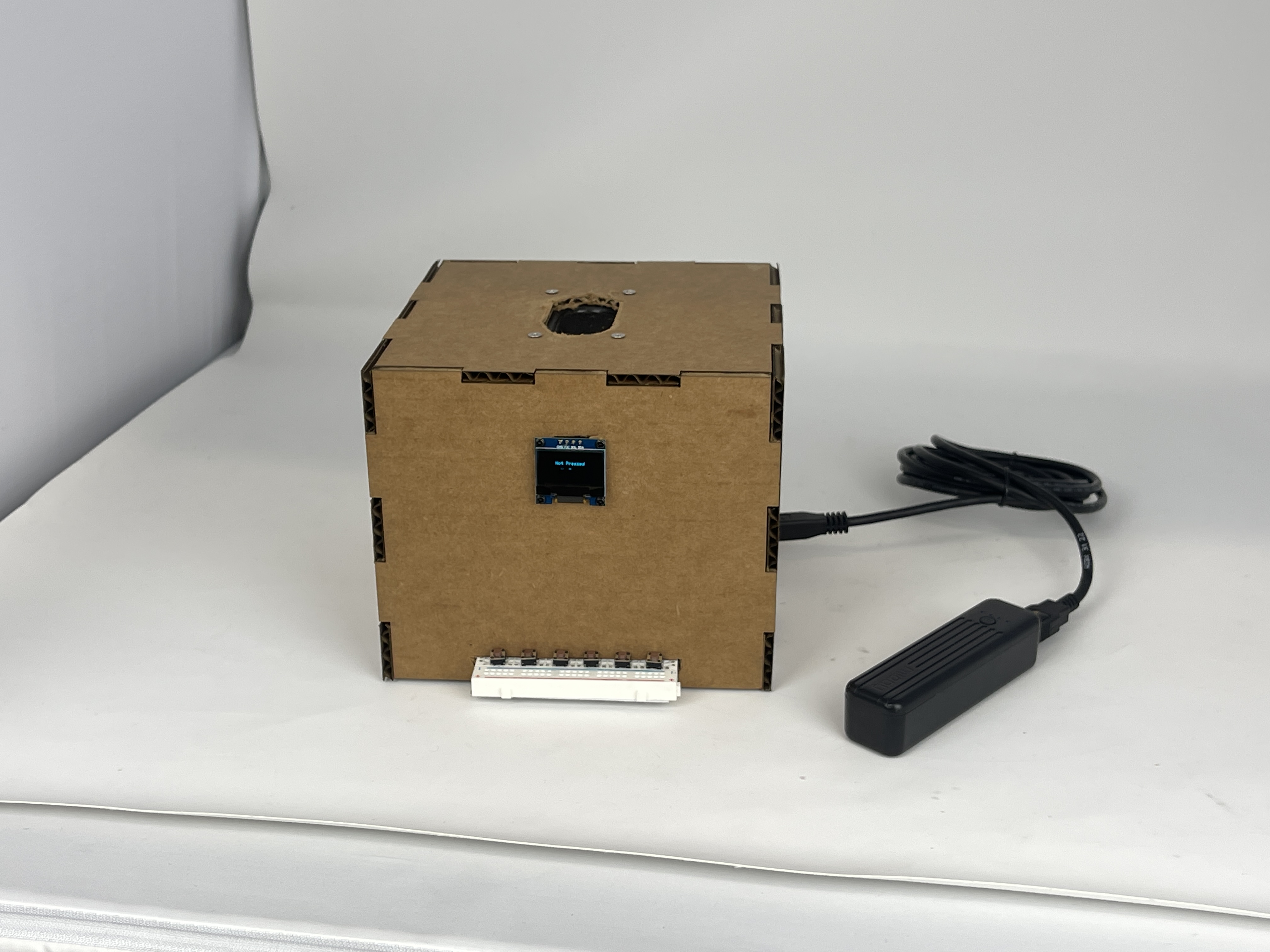
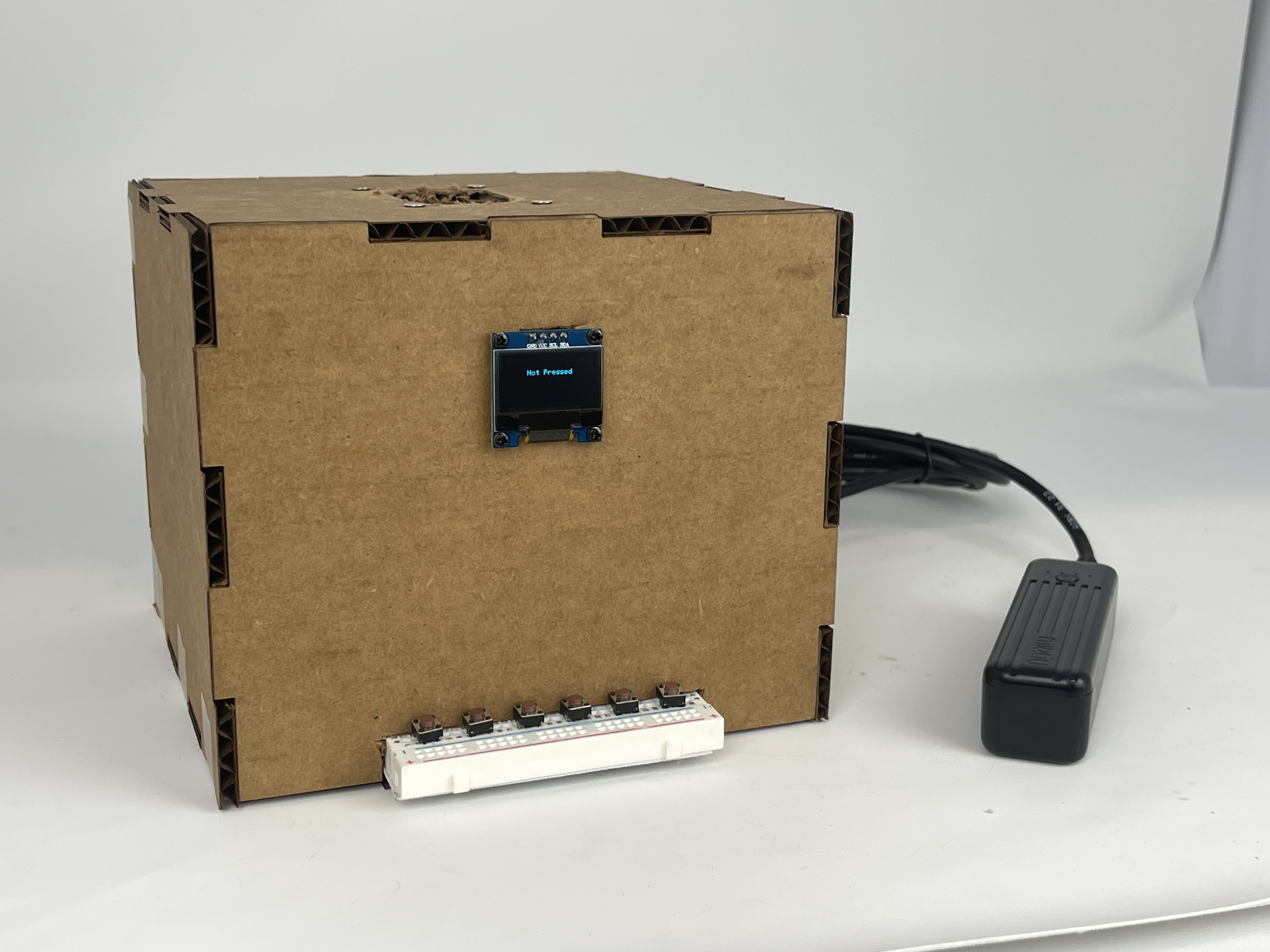
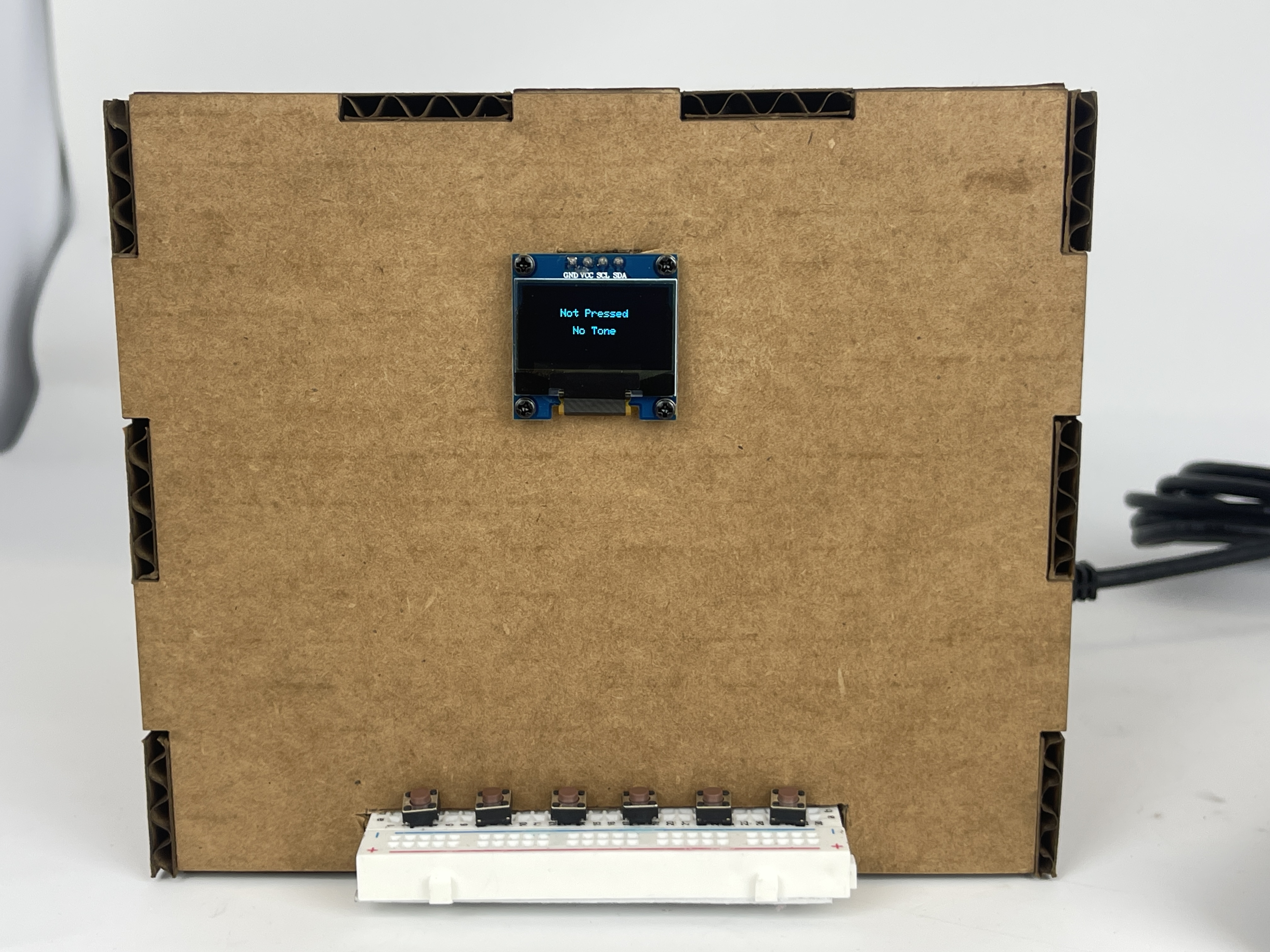
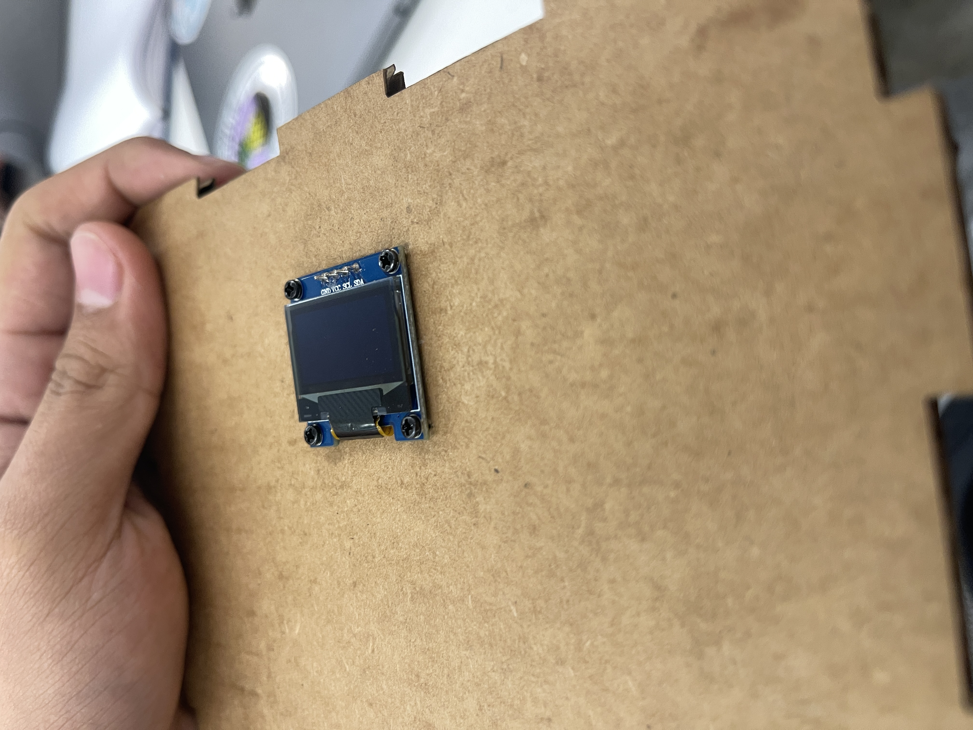
After successfully completing the circuitry/software part of the project, I needed to create a contraption that essentially stored all of the microcontrollers and wires in one place, while also letting the user interact with the device. I planned to create a box; using my knowledge within Fusion360, I created a press-fit constructed box, and used cardboard as my medium.
I also screwed in the OLED Screen into the front of the cardboard press-fit.
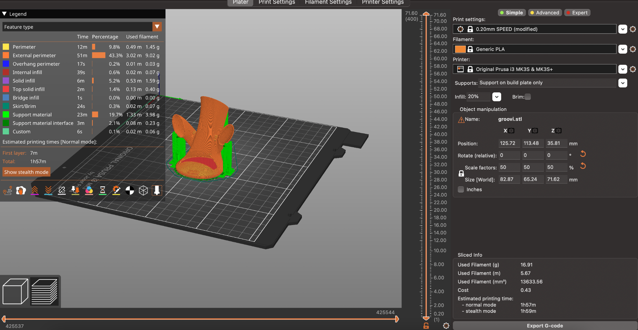
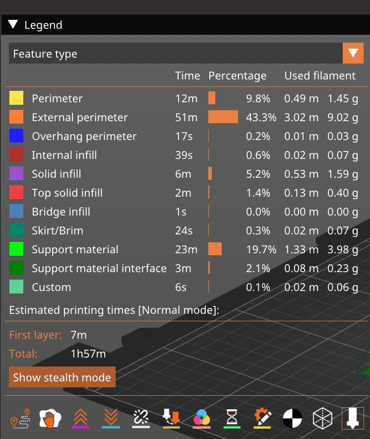
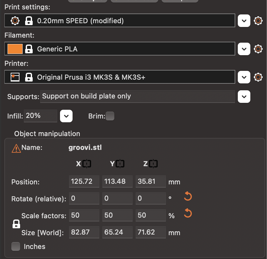
3D Printing:
I thought of trying to implement the 3D printer with a problem that I was experiencing with the system. And I found that one problem, or better to say, one limitation of my project, was not being able to fully use the amplifer to control the volume of the speaker. Therefore, I tried to create a sort of 3D-printed sound amplifier, which would take in the sound produced by the speaker, and make it louder to the human ear.
Here are some pictures:
Final Product: