Throughout this week, we were taught how to build specific circuits, and implement different types of resistors to manipulate the circuit to measure a specific value. Some of the resistors that we explored included thermistors for temperature changes, force-sensitive resistors for pressure/force detection, phototransistors/photresistors for light detection, and accelerometers for motion.
1. Photoresistor Circuit
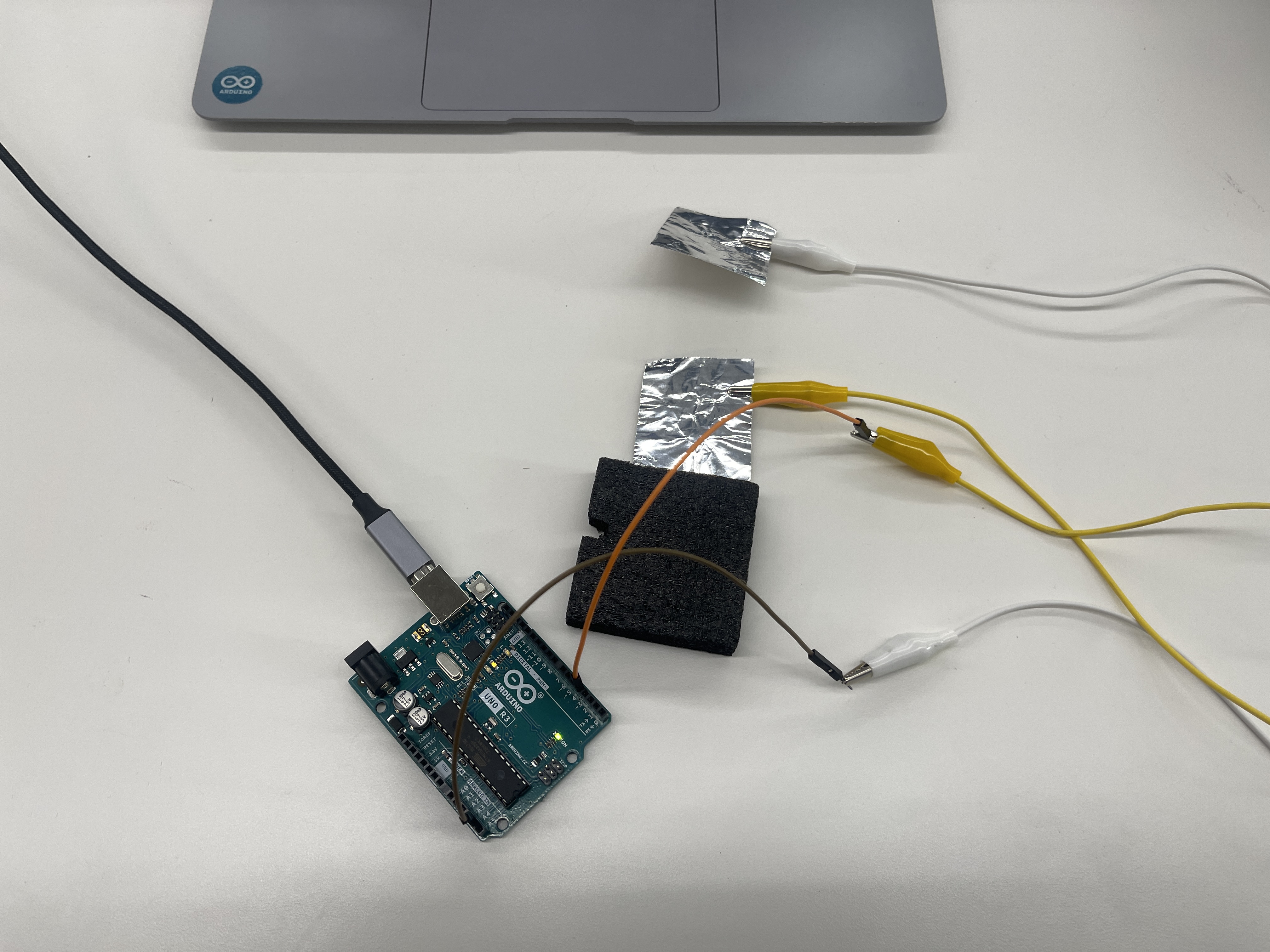
For the first assignment, we were tasked to use a given sensor to measure a physical quantity using the Arduino Uno Microcontroller. Thus, I attempted to use a photoresistor to measure the amount of voltage that is transmitted through a circuit. The picture on the bottom left depicts the circuit model that I followed, and the picture on the bottom right shows how I implemented this model onto an Arduino.
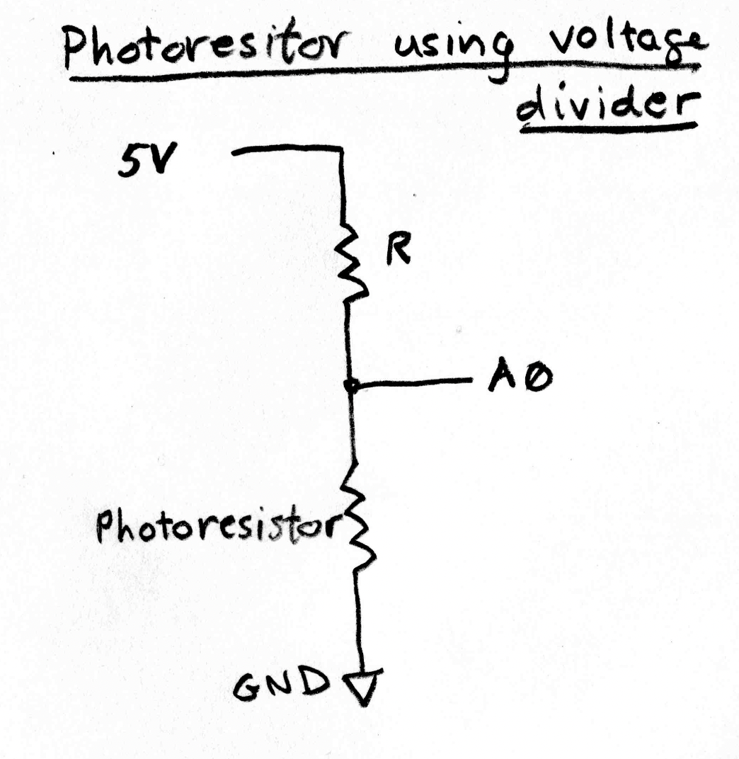
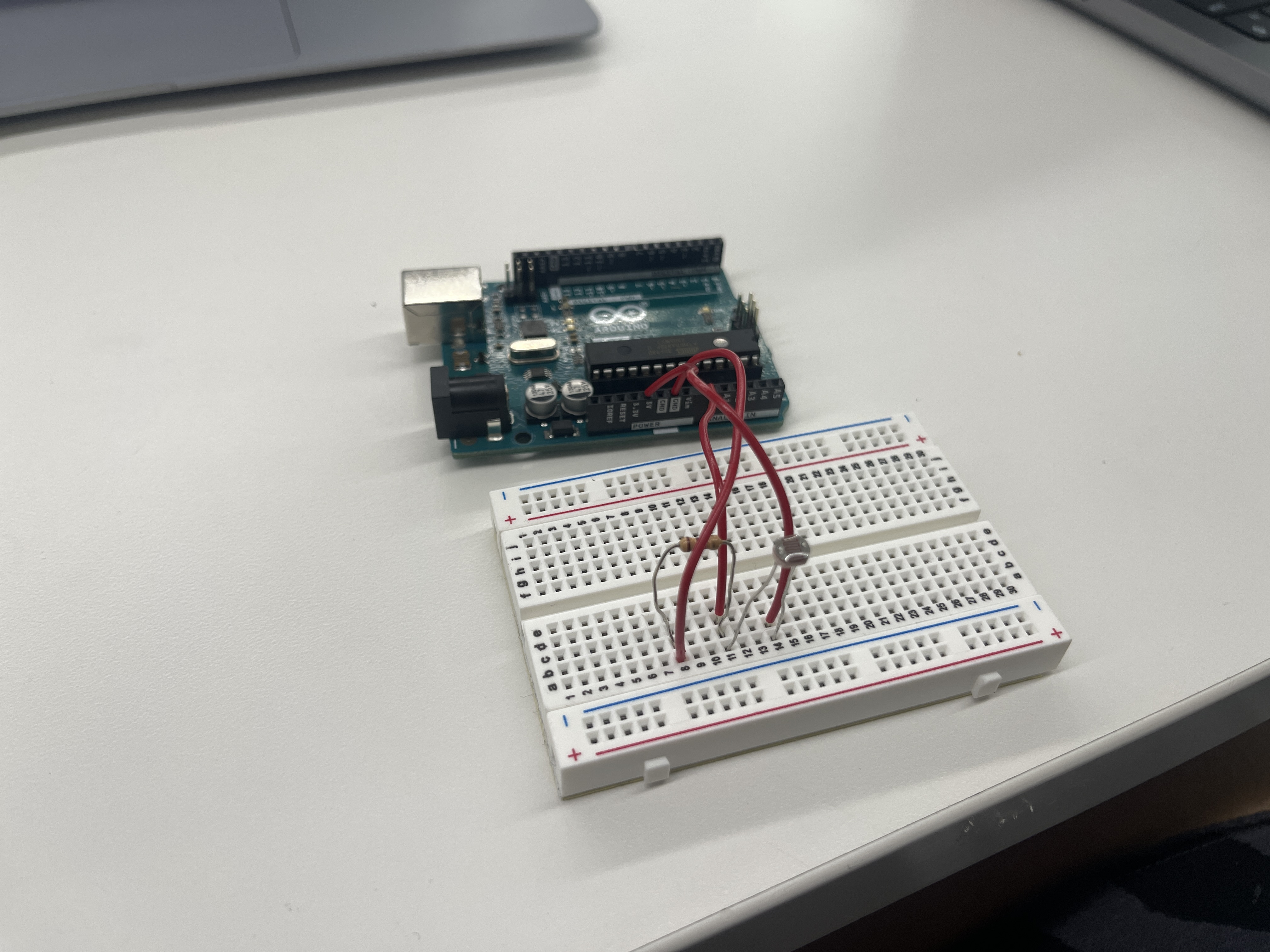
After completing the circuitry, I installed a program into the Arduino that detects the change in resistance within the circuit. The reason for this is because the photoresistor within the circuit changes its resistance as a function of light. As it receives more light its resistance decreases, and the voltage at the point labeled A0 decreases. Below is the code that I used for this:
    /*
        AnalogReadSerial

                Reads an analog input on pin 0, prints the result to the Serial Monitor.
                Graphical representation is available using Serial Plotter (Tools > Serial Plotter menu).
                Attach the center pin of a potentiometer to pin A0, and the outside pins to +5V and ground.

                This example code is in the public domain.

                https://www.arduino.cc/en/Tutorial/BuiltInExamples/AnalogReadSerial
            */

            // the setup routine runs once when you press reset:
            void setup() {
                // initialize serial communication at 9600 bits per second:
                Serial.begin(9600);
            }

            // the loop routine runs over and over again forever:
            void loop() {
                // read the input on analog pin 0:
                int sensorValue = analogRead(A0);
                // print out the value you read:
                Serial.println(sensorValue);
                delay(1);  // delay in between reads for stability
            }
Within this program, the setup() function initailizes the communication between the Arduino Uno Microcontroller and the connected photoresistor. This connection itself allows for real-time communication, enabling the Arduino to simulataneously send and receive data between the photoresistor and the computer.
Furthermore, the loop() function in this code allows the Arduio to continously read the analog input from pin A0 using the analogRead(A0) function, which measures the voltage level on the pin. This value of voltage is then stored in the variable sensorValue. The program then continues to print this voltage value (sensorvalue) to the Serial Monitor within the Arduino IDE application. This allows for us to observe the values received by the photoresistor in real-time.
Below are two videos of the photoresistor working:
Using my iPhone flashlight, I was able manipulate the amount of voltage that was being transmitted across the circuit. By putting the flashlight closer to the photoresistor, the photoresistor recorded up an increased amount of voltage. Vice versa; when the flashlight got further away from the photoresistor, the values recorded by the resistor decreased.
Through the visualization of the graph, I discovered the maximum value recorded by the photoresistor was approximately 450.
Keep in mind that this value was recorded with the iPhone flashlight directly above the photoresistor, allowing the photoresistor to measure the maximum amount of voltage that could be recorded through the photoresistor. In addition, the minimum value recorded was zero.2. Capacitive Sensor
Another part of this week's assignment was to create a capacitive sensor. In my case, I created a capacitive sensor that uses two metallic sheets to vary the amount of voltage/current that is passing through the circuit. In this particular case, the two metallic sheets act as conductive elements; meaning that when they are brought closer to one another, the resulting capacitance between them increases. An increase in capacitance therefore causes the amount of voltage passing through the circuit to increase. Below is a picture of the capacitive sensor: